Device and method for manufacturing tube bodies

a tube body and tube body technology, applied in the direction of layered products, control lamination, chemical instruments and processes, etc., can solve the problems of waste generation, defective tube bodies, deficient tightness and/or pressure resistance of tube bodies, etc., and achieve the effect of high passage barrier

Active Publication Date: 2018-04-03
PACKSYS GLOBAL SWITZERLAND
View PDF7 Cites 0 Cited by
  • Summary
  • Abstract
  • Description
  • Claims
  • Application Information

AI Technical Summary

Benefits of technology

[0011]Proceeding from the presented prior art, the invention is based on the problem of improving a device and a method for the manufacture of circumferentially closed tubular tube bodies according to the introductory clauses of the independent claims so that the quality of the manufactured tubes is maximized and, at the same time, the expenditure for smooth operation is minimized.
[0019]First control means are provided, which keep the substrate web in a given position before the tube forming means transversely to the conveying direction, by actuating the positioning means as a function of the measured values of the first sensor means, so that they balance out deviations from the required position, if necessary. It is thus made possible to avoid from the outset fluctuations at the contact position owing to fluctuations in the substrate web position before the tube forming means.
[0022]By the invention, it is made possible to keep the contact region permanently in the welding position in an automated manner—without manual interventions of operating personnel—, or respectively to react more quickly to any deviations. This reduces the waste by “mis-welding” outside the contact region. Generally the invention improves the quality of the weld seam and therefore the quality of the tubes, in particular their resilience.
[0028]Furthermore, it is conceivable that the first control means actuate further positioning means, which are mounted upstream or downstream of the positioning means. Hereby, at the same time, the advantages of the controlling of the web edge position, known from the prior art, by sensor means close to the positioning means and the advantages of the controlling of the substrate position according to the invention with sensor means and and / or after the shaping region (which also take into consideration the influences of the tube forming means onto the substrate) can be achieved.
[0030]Here, a bypass can be provided, so that the outer control circuit is (effectively) the sole control circuit, and the second control means directly actuate the positioning means, whereby for instance in particular cases a faster reaction can be achieved to a running apart of welding circumferential position and contact region. Furthermore, a defect of the inner control circuit can therefore also be balanced out promptly.

Problems solved by technology

By several different influences, the contact region can move away from the welding position which is defined by the welding device, frequently resulting in defective tube bodies.
When the contact region runs adjacent to or only partially through the welding region, this can result in a deficient tightness and / or pressure resistance of the tube bodies.
This is costly, is time-consuming (therefore generates waste) and requires experienced personnel who are in addition frequently involved periodically in monitoring tasks.

Method used


Image

  • Device and method for manufacturing tube bodies
  • Device and method for manufacturing tube bodies
  • Device and method for manufacturing tube bodies

Examples


Embodiment Construction

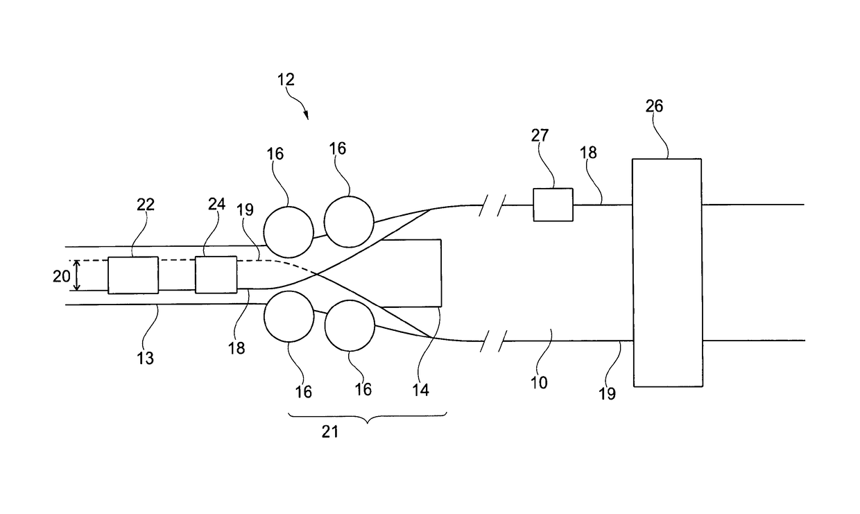
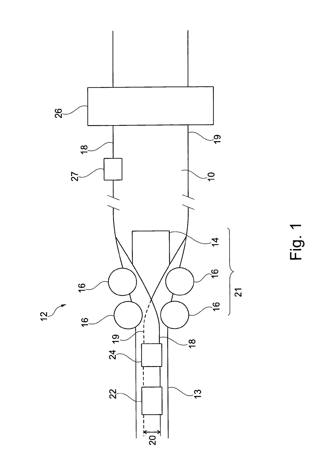
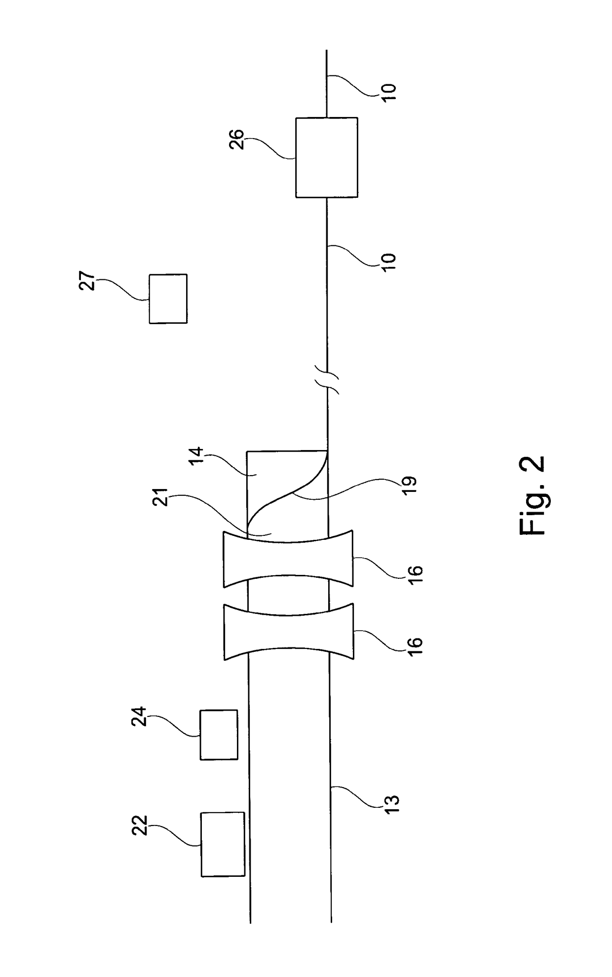
[0050]FIG. 1 shows in a top view a device according to a preferred embodiment of the invention. FIG. 2 shows the same device in a longitudinal view.

[0051]A substrate web 10 is illustrated, with its two longitudinal edges 18 and 19, which are at least partially parallel. The substrate web 10 is formed by tube forming means 12 into a tubular form 13 around a cylindrical mandrel 14. The tube forming means 12 comprise concave guide rolls 16.

[0052]During the forming process, a contact region 20 forms between the longitudinal edges 18 and 19. Welding means 22, for example in the form of a high frequency welding device, and second sensor means 24 are arranged over the contact region 20.

[0053]The second sensor means 24 are arranged here directly over the contact region, which is configured as an overlapping region, however it is alternatively also conceivable to arrange the second sensor means 24 shortly before the contact region, for instance as in the position 24b illustrated in dashed li...


PUM

PropertyMeasurementUnit
distanceaaaaaaaaaa
distanceaaaaaaaaaa
distanceaaaaaaaaaa

Abstract

A device for manufacturing circumferentially closed tubular tube bodies, comprising conveying means for conveying the substrate in a conveying direction, and also comprising tube-forming means which are designed to form a web-like substrate, which has a first and a second longitudinal edge, into a tubular form in which, in the circumferential direction, the first and the second longitudinal edge form or delimit a contact region, in particular abutting or overlapping region, which extends in the conveying direction, wherein the tube-forming means effect the shaping of the substrate into the tubular form in a shaping region and comprise welding means for welding the tubular form at a weld circumferential position, first sensor means, which are upstream of the shaping region; in the conveying direction, for detecting the position of the substrate web, setting means for setting the position of the substrate web transversely with respect to the conveying direction, and first control means which are designed to actuate the setting means, taking into consideration the measurement values from the first sensor means, such that the web-like substrate is held in a setpoint position transversely with respect to the conveying direction or such that the web-like substrate is adjusted in the direction of the setpoint position.

Description

BACKGROUND OF THE INVENTION[0001]The invention relates to a device and a method for the manufacture of circumferentially closed tubular tube bodies.[0002]Manufacturing plants for the manufacture of tubes are known from the prior art. For the manufacture of tube bodies, a web-shaped substrate is conveyed by conveying means, for example rolls and / or rollers, in a conveying direction and is formed by tube forming means, for example by rolls, rollers and / or stationary deflector plates, into a tubular form around a cylindrical mandrel. In so doing, the two marginal regions, which respectively adjoin one of the longitudinal edges of the substrate web, contact one another, in the tubular form in a contact region, for instance in the form of an overlapping region, in which the two marginal regions overlap one another, or a contact position, for instance in the form of an abutting edge, in which the two longitudinal edges of the substrate lie against one another (wherein in the following the...

Claims


Application Information

Patent Timeline
Patent Type & Authority Patents(United States)
IPC IPC(8): B32B41/00B29C65/00B29C53/54B29C65/02B29C65/78B29C65/04
CPCB32B41/00B29C53/54B29C65/02B29C65/7832B29C65/7894B29C66/1122B29C66/4322B29C66/49B29C66/836B32B2309/72B32B2041/04B29C66/72341B29C66/72321B29C66/71B29C65/04B29K2077/00B29K2023/086B29K2067/003
Inventor LAUBLI, JULIUS
Owner PACKSYS GLOBAL SWITZERLAND
Why Eureka
Try Eureka