
Process cartridge and spacer for same

Inactive Publication Date: 2005-09-20
CANON KK
View PDF32 Cites 92 Cited by
  • Summary
  • Abstract
  • Description
  • Claims
  • Application Information

AI Technical Summary

Benefits of technology

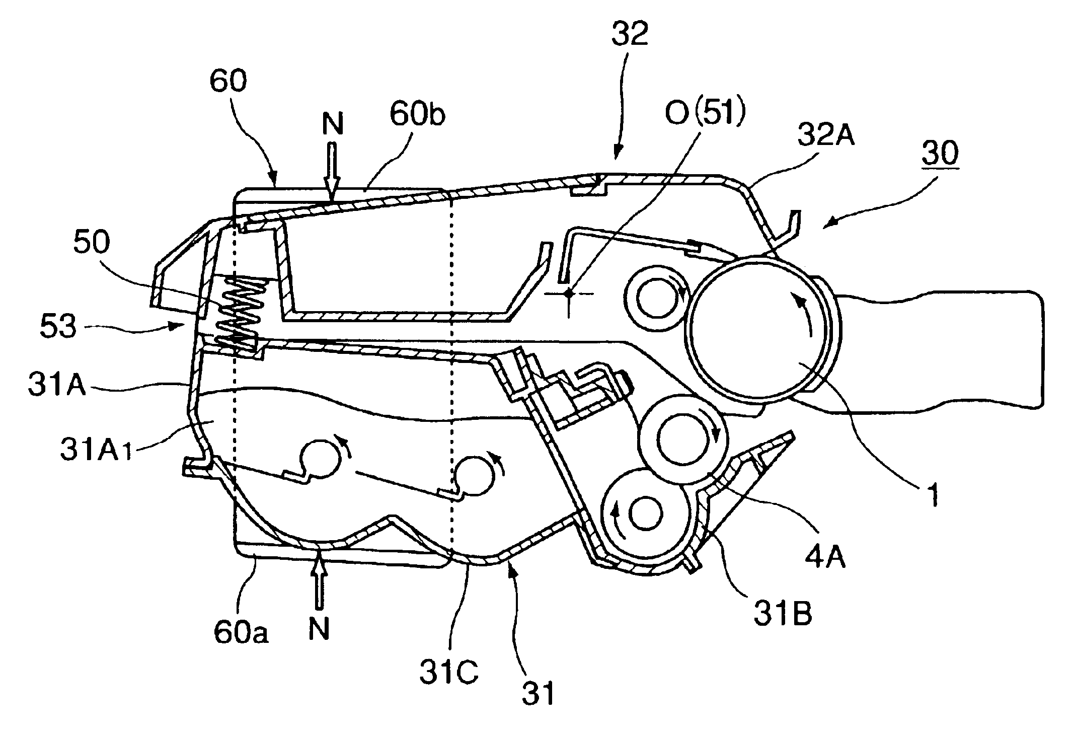
[0009]The primary object of the present invention is to provide: a process cartridge in which a gap can be maintained between an electrophotographic photoconductive drum and a development roller; an electrophotographic image forming apparatus in which such a process cartridge can be removably mountable; and a gap-maintaining member.
[0011]Another object of the present invention is to provide: a process cartridge in which damage to the peripheral surface of an electrophotographic photoconductive drum and / or a development roller is prevented by keeping the electrophotographic photoconductive drum apart from the development roller, an electrophotographic image forming apparatus in which such a process cartridge is removably mountable; and a gap-maintaining member.
[0013]Another object of the present invention is to provide: a process cartridge in which there is no possibility that contact between a development roller and a photoconductive drum will make the development roller conform in shape to the peripheral surface of the photoconductive drum, during the shipment of the process cartridge; and a gap-maintaining member for such a process cartridge.

Problems solved by technology

When an image is formed with the use of a development roller having been deformed as described above, there is the possibility that as the deformed portion of the development roller is brought by the rotation of the development roller to the contact area between the development roller and photoconductive drum, the state of the contact area between the development roller and photoconductive drum will change, resulting in unsatisfactory development.

Method used


Image

  • Process cartridge and spacer for same
  • Process cartridge and spacer for same
  • Process cartridge and spacer for same

Examples


Embodiment Construction

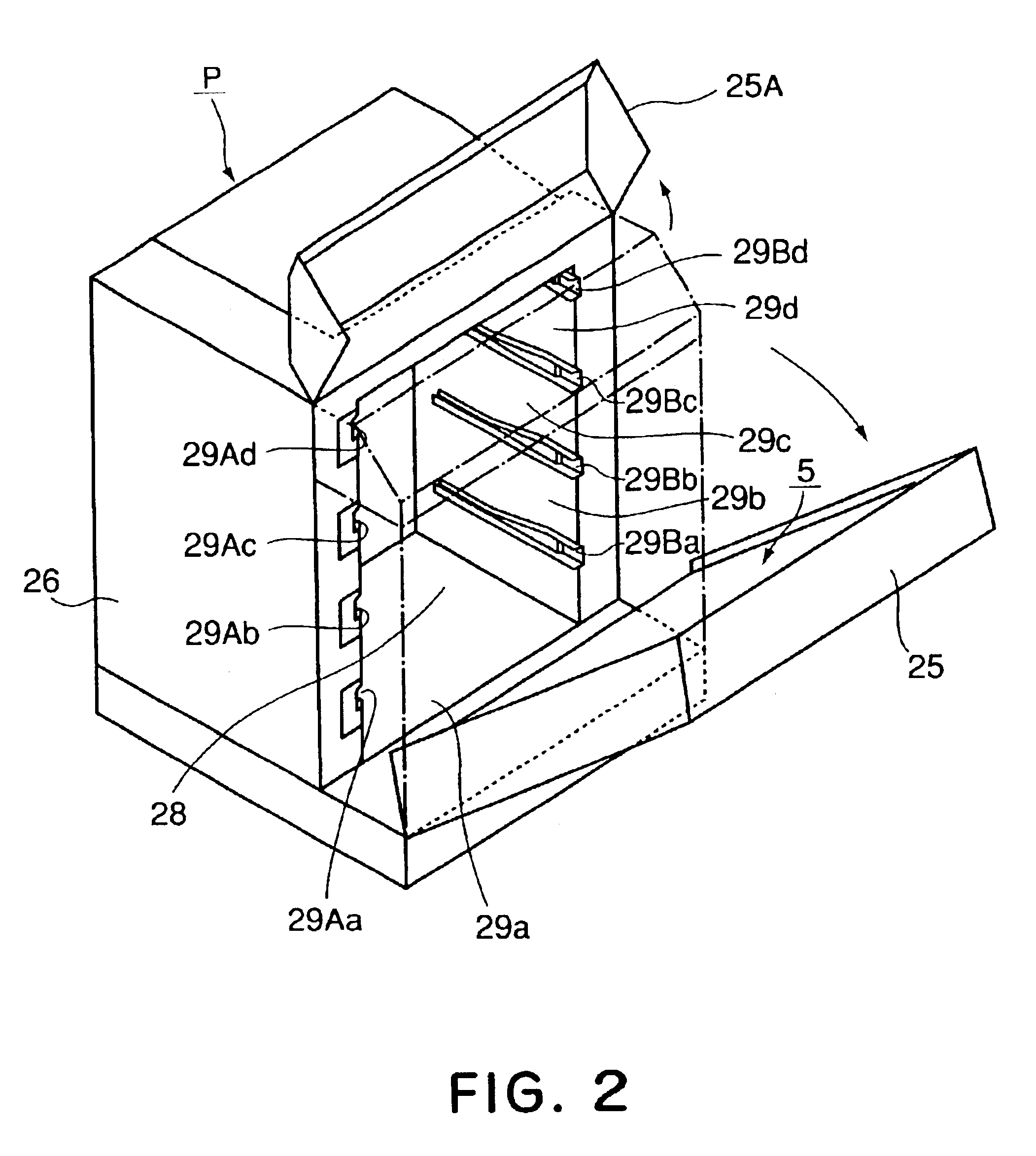
[0032]Hereinafter, the preferred embodiments of the present invention will be described with reference to the appended drawings.

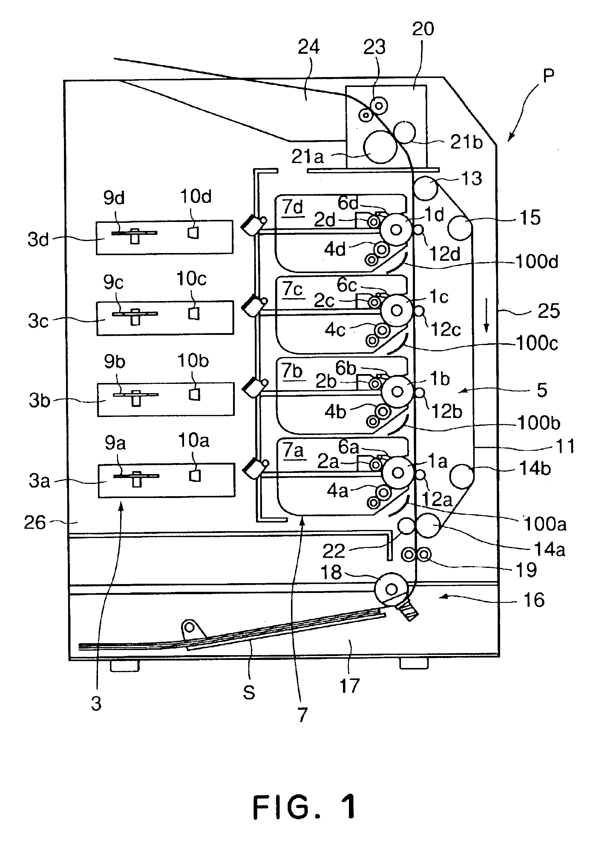
[0033]First, referring to FIG. 1, the general structure of a typical multicolor image forming apparatus in accordance with the present invention, and the image forming operation thereof, will be described. FIG. 1 is a vertical sectional view of a full-color image forming apparatus as an embodiment of an image forming apparatus in accordance with the present invention, for showing the general structure thereof.

[0034]The image-forming apparatus in FIG. 1 has a plurality (four in FIG. 1) of image-formation stations, which are vertically stacked, and each of which has a photoconductive drum 1 functioning as an image bearing member. The photoconductive drum 1 (1a, 1b, 1c, 1d) in each image-formation station is rotationally driven by an unshown driving means in the counterclockwise direction in FIG. 1. Disposed around the photoconductive drum 1 (1a, 1b, 1c, 1d) i...


PUM


Abstract

A process cartridge detachably mountable to a main assembly of an image forming apparatus includes an electrophotographic photosensitive drum; a developing roller for developing an electrostatic latent image formed on the drum; a first frame supporting the drum; a second frame supporting the developing roller; a coupling member for coupling the first frame and the second frame such that developing roller and the drum contact each other or are spaced from each other; an urging member for urging the drum and the developing roller toward each other; a spacer member for maintaining the drum and the developing roller spaced from each other or the distance between centers of the drum and the developing roller to be larger than the distance therebetween during an image forming operation. The spacer member supports the first frame and second frame at least at longitudinally extending surfaces of the process cartridge, and is detachable from the process cartridge.

Description

FIELD OF THE INVENTION AND RELATED ART[0001]The present invention relates to a process cartridge for an electrostatic image forming apparatus, for example, a printer, a copying machine, and the like. It also relates to a member for maintaining a predetermined gap between an electrophotographic photoconductive drum and a development roller, in a process cartridge. Further, it relates to an image forming apparatus.[0002]Hereafter, a process cartridge is a cartridge in which an electrophotographic photoconductive member, and at least a development roller functioning as a developing means, are integrally disposed, and which is removably mountable in a main assembly of an image forming apparatus. It also refers to a cartridge in which an electrophotographic photoconductive member, a developing means, and at least one of a charging means and a cleaning means, are integrally disposed, and which is removably mountable in a main assembly of an image forming apparatus.[0003]An electrophotogra...

Claims


Application Information

Patent Timeline
IPC IPC(8): G03G21/18G03G15/08
CPCG03G21/1825G03G2221/1861G03G15/00
Inventor KAWAI, TACHIOARIMITSU, TAKESHIMAESHIMA, HIDEKI
Owner CANON KK
Learn More