Method and apparatus for allocating network resources and changing the allocation based on dynamic workload changes

a network resource and dynamic workload technology, applied in the field of computer implemented methods and apparatuses, can solve the problems of not providing a minimum amount of network resources for a particular process, unable to ensure that a particular process will have the minimum required resources, and unable to run efficiently, and none of the allocating systems known to the inventors. provide a minimum amount of network resources

Inactive Publication Date: 2005-09-20
TERADATA US
View PDF21 Cites 117 Cited by
  • Summary
  • Abstract
  • Description
  • Claims
  • Application Information

AI Technical Summary

Benefits of technology

[0015]Still other objects and advantage of the present invention will become readily apparent to those skilled in the art from following detailed description, wherein the preferred embodiments of the invention are shown and described, simply by way of illustration of the best mode contemplated of carrying out the invention. As will be realized, the invention is capable of other and different embodiments, and its several details are capable of modifications in various obvious respects, all without departing from the invention. Accordingly, the drawings and description thereof are to be regarded as illustrative in nature, and not as restrictive.

Problems solved by technology

None of the foregoing patents ensure that a particular process will have the minimum required resources.
Although these allocating systems reallocate computer and / or network resources to achieve maximum efficiency and utilization of computers and processors, situations occur where a high priority process or group of processes require a minimum amount of network resources.
For example, if one of the computers on a computer network fails, and a network server redistributes the processing load among the remaining network computers, this high priority process or group of processes may not have sufficient network resources allocated to either run on the network, or run efficiently.
None of the allocating systems known to the inventors provide a minimum amount of network resources for a process or group of processes.

Method used


Image

  • Method and apparatus for allocating network resources and changing the allocation based on dynamic workload changes
  • Method and apparatus for allocating network resources and changing the allocation based on dynamic workload changes
  • Method and apparatus for allocating network resources and changing the allocation based on dynamic workload changes

Examples


Embodiment Construction

[0022]A method and apparatus for allocating network resources and changing the allocation based on dynamic workload changes according to the present invention are described. In the following description, for purposes of explanation, numerous specific details are set forth in order to provide a thorough understanding of the present invention. It will be apparent, however, that the present invention can be practiced without these specific details. In other instances, well-known structures and devices are shown in block diagram form in order to avoid unnecessarily obscuring the present invention.

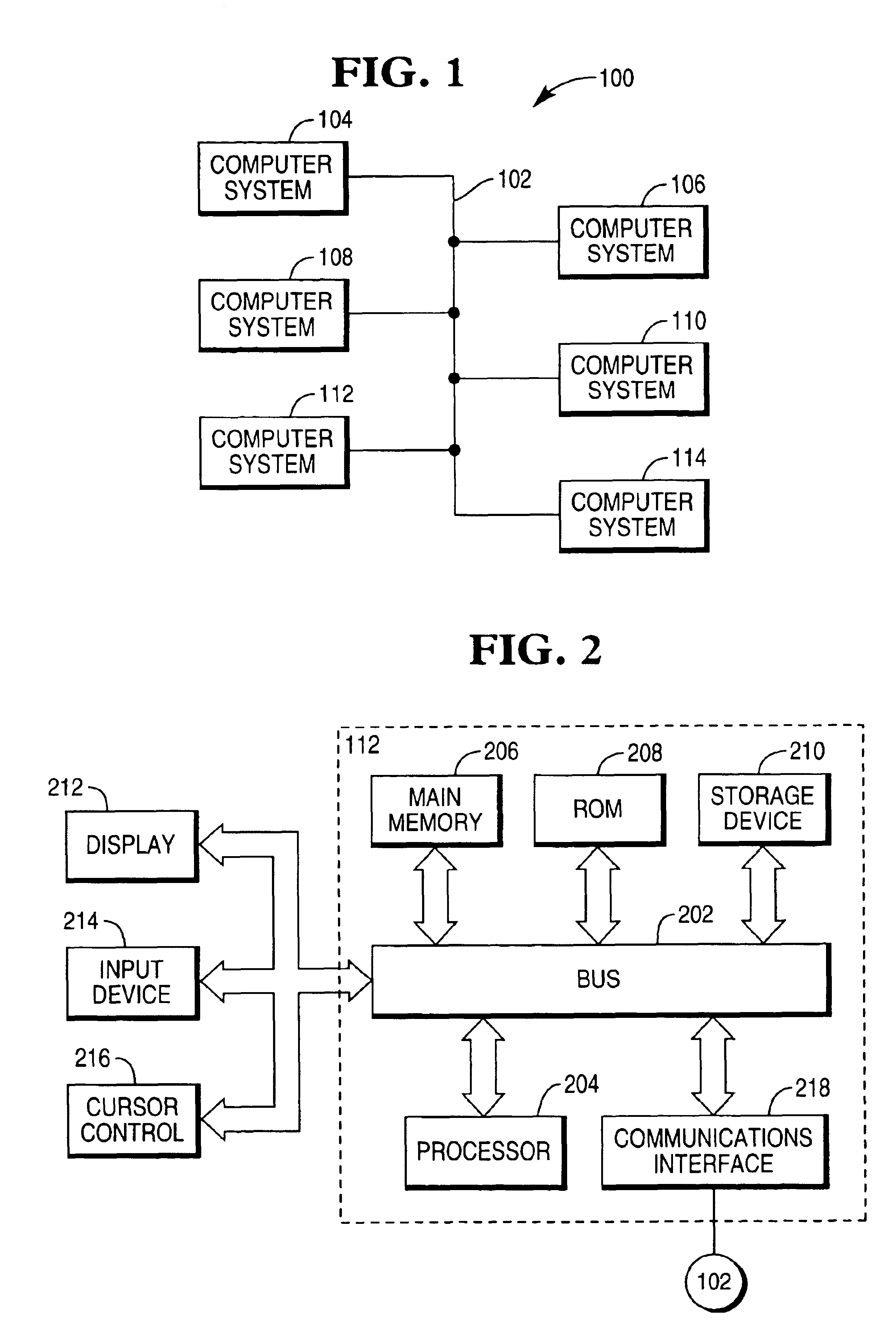
[0023]FIG. 1 is a block diagram of an exemplary computer network 100 including a plurality of computer systems serving as network devices 104, 106, 108, 110, 112 on which an embodiment of the invention can be used. The network devices 104, 106, 108, 110, 112 can be identical or different and can include devices such as hosts, servers and personal computers. The present invention is usable on su...


PUM


Abstract

A method of allocating and distributing processes to network resources. The amount of network resources is determined for each process or groups of processes to be executed on the computer network. A minimum source allocation is provided for one or more of the processes. Each of the network resources is monitored for resource use. If necessary, a resource allocator redistributes network resources in accordance with the minimum resource allocation.

Description

FIELD OF THE INVENTION[0001]The present invention relates to a computer implemented method and apparatus for distributing computer resources on a network, and more particularly, to a method and apparatus for allocating network resources and for changing the allocation based on dynamic workload changes.BACKGROUND OF THE INVENTION[0002]It is desirable to distribute the processing load among multiple computers and processors in a computer network. The function of distributing the processing load among the multiple computers and processors in the network is often referred to as dynamic load balancing or processor assignment. Load balancing is frequently based on processor efficiency, reliability and usage.[0003]An example of load balancing for one computer is disclosed in U.S. Pat. No. 5,675,797 where resources are initially allocated into buffer pools. To enhance system performance, buffer pool resources are reallocated based on a performance index. For example, the buffer pool with th...

Claims


Application Information

Patent Timeline
Patent Type & Authority Patents(United States)
IPC IPC(8): G06F9/46G06F9/50
CPCG06F9/5016G06F9/5083G06F2209/508
Inventor BOLAND, VERNON K.
Owner TERADATA US
Why Eureka
Try Eureka