Acoustic wave touch detecting apparatus

a detection apparatus and acoustic wave technology, applied in the direction of acceleration measurement using interia force, printed circuit non-printed electric components association, instruments, etc., can solve the problems of difficult wire arrangement, electromagnetic waves radiating to the exterior from signal wires, and adds to the cost of the apparatus, so as to achieve superior anti-electromagnetic interference (emi) properties and low cost

Inactive Publication Date: 2005-09-27
ELO TOUCH SOLUTIONS INC
View PDF6 Cites 192 Cited by
  • Summary
  • Abstract
  • Description
  • Claims
  • Application Information

AI Technical Summary

Benefits of technology

[0008]The present invention has been developed in view of the above points. It is an object of the present invention to provide an acoustic wave contact detecting apparatus, which is superior in anti-Electromagnetic Interference (EMI) properties, at low cost.
[0024]In the acoustic wave contact detecting apparatus of the present invention, at least one of the acoustic wave generating means and the detector are connected the controller by flexible planar wiring. The flexible planar wiring is of a wiring pattern in which a grounding wire is provided on at least one side of a signal wire. Therefore, the signal wire is electromagnetically shielded by the grounding wire, improving the anti-EMI properties of the acoustic wave contact detecting apparatus. In addition, as the necessity for an additional shielding structure is obviated, the cost of the apparatus is reduced.
[0025]Further, a construction may be adopted wherein the flexible planar wiring comprises a signal wire group in which a plurality of the signal wires are arranged; and grounding wires at both sides of the signal wire group. In this case, the group of signal wires is enabled to be collectively and efficiently shielded, further improving the anti-EMI properties. This construction also enables miniaturization of the flexible planar wiring. The miniaturization of FPC's further contribute to reduction in cost thereof, as the cost of FPC's is substantially proportional to the area thereof.

Problems solved by technology

However, in the case that the periphery of the substrate is covered by bezels and the like, it is difficult to arrange the wires due to the scarcity of space.
In addition, there is a problem that electromagnetic waves radiate to the exterior from the signal wires.
However, this construction adds to the cost of the apparatus, due to the necessity of separate members.

Method used


Image

  • Acoustic wave touch detecting apparatus
  • Acoustic wave touch detecting apparatus
  • Acoustic wave touch detecting apparatus

Examples


Embodiment Construction

[0044]Preferred embodiments of the acoustic wave contact detecting apparatus (hereinafter, simply referred to as “apparatus”) will be described with reference to the attached drawings.

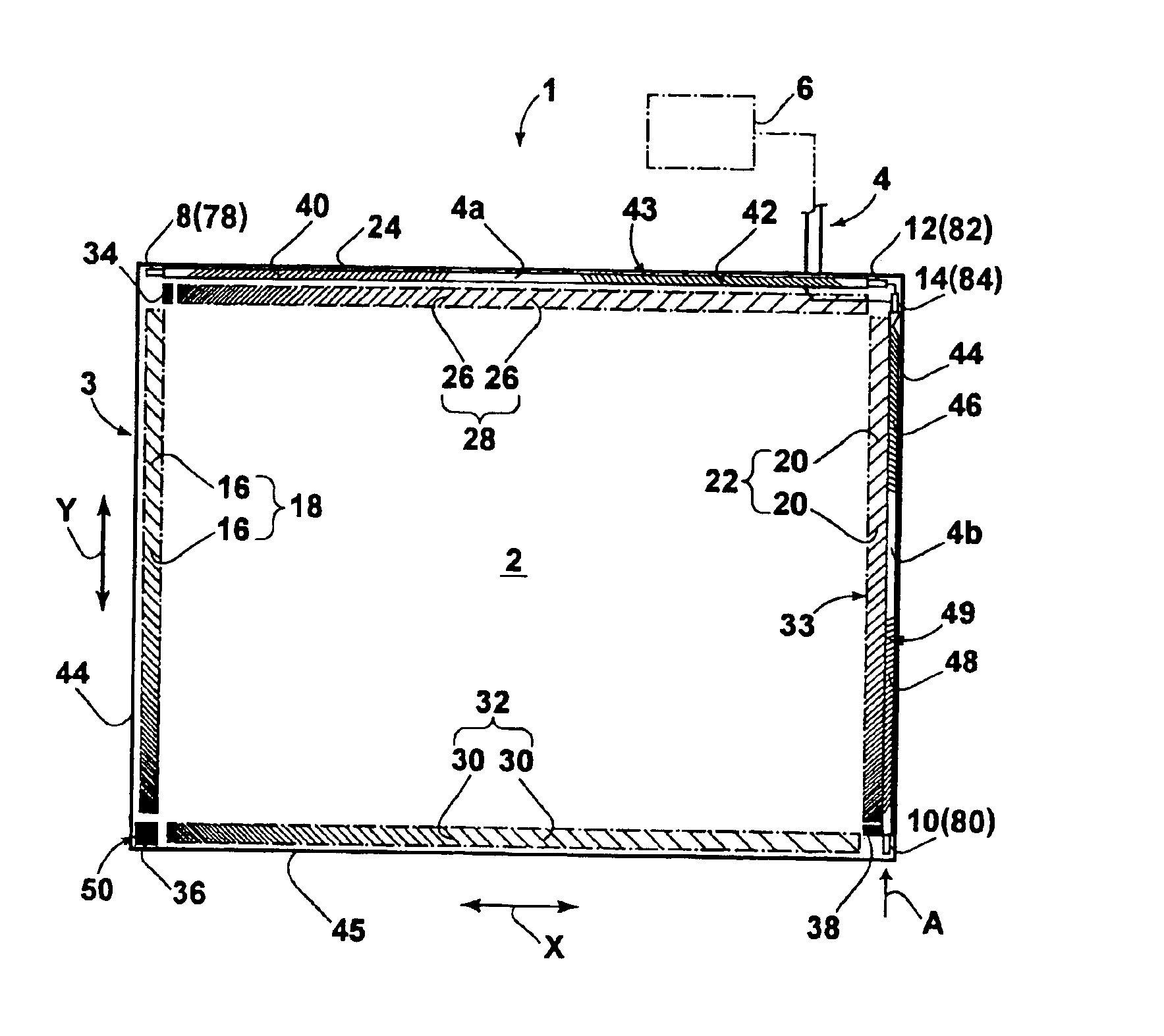
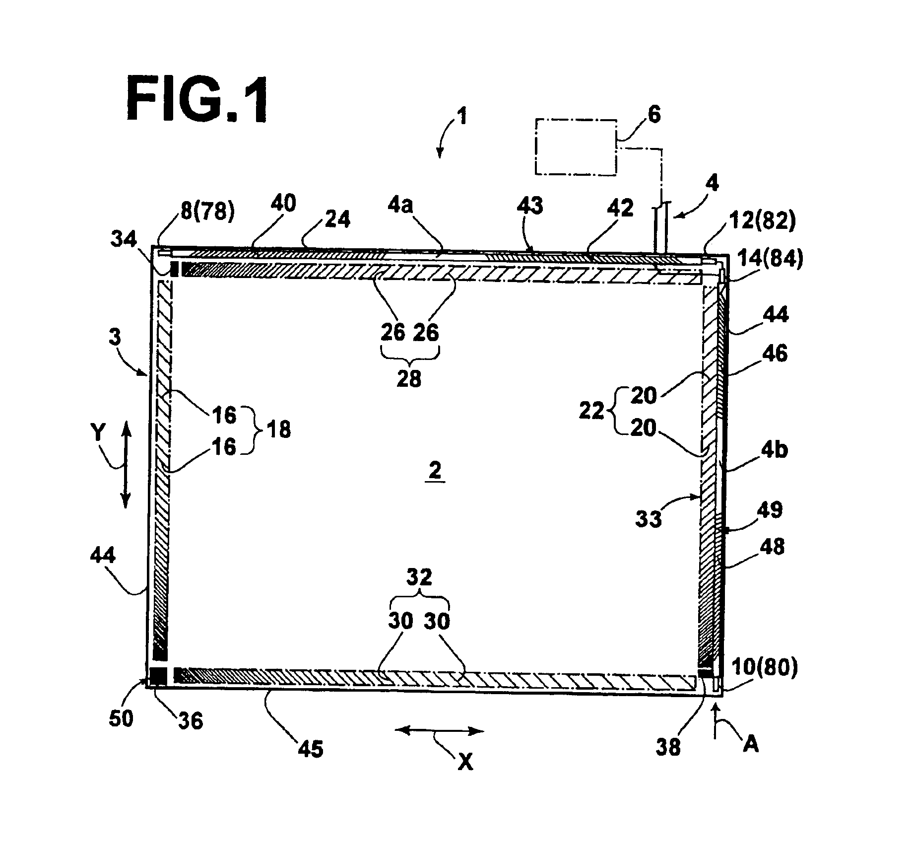
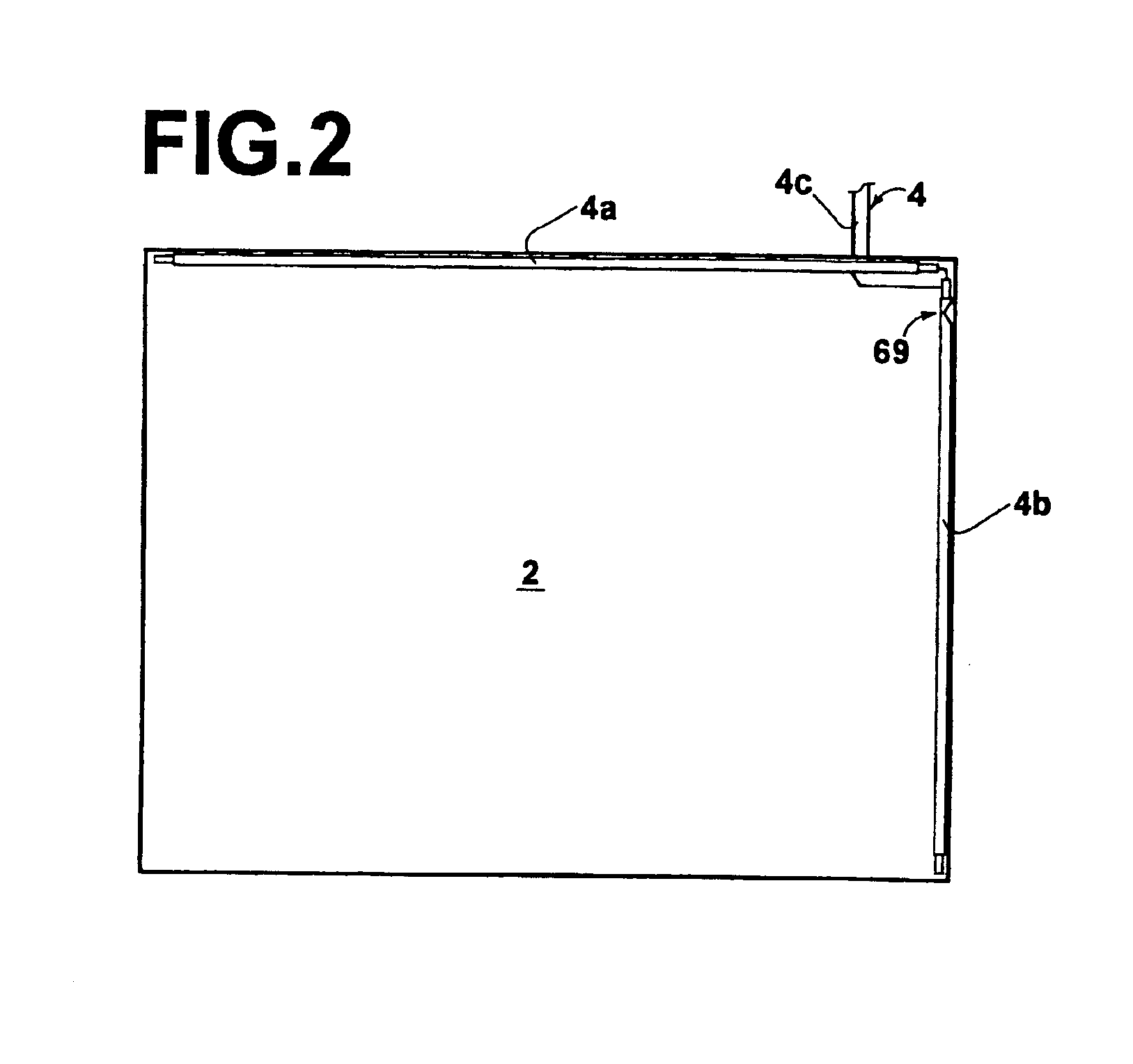
[0045]FIG. 1 is a front view of a touch panel 3, to be utilized in an apparatus 1. As shown in FIG. 1, the touch panel 3 comprises: a substrate 2 formed by a rectangular glass plate; a Flexible Printed Circuit 4 (FPC) mounted on the substrate 2; and a controller 6, which is electrically linked to the FPC 4.

[0046]The FPC 4 is branched into an FPC branch 4a and an FPC branch 4b. The FPC branch 4a extends along the horizontal direction of the substrate 2, that is, the X axis direction indicated by the arrow X. The FPC branch 4b extends along the vertical direction of the substrate perpendicular to the X axis, that is, the Y axis direction indicated by the arrow Y. Converters (bulk wave generating means) 8 and 10 for generating ultrasonic waves are mounted on the FPC 4. In addition, converters (detectors) ...


PUM


Abstract

An FPC is constructed of two FPC branches, and a connection line that connects to a controller. Printed wiring of the connection line includes ten printed wires. The central four printed wires are signal reception wires, which are connected to two converters (sensors). Grounding wires are provided on both sides of the four signal reception wires. Two outer signal wires are provided adjacent to the grounding wires, respectively toward the outsides thereof. Further, two more grounding wires are provided adjacent to the outer signal wires, respectively on the outsides thereof. This construction results in shielding of all of the signal wires. This relationship is maintained in the FPC branches as well.

Description

BACKGROUND OF THE INVENTION[0001]1. Field of the Invention[0002]The present invention relates to an acoustic wave contact detecting apparatus, such as an ultrasonic touch panel.[0003]2. Description of the Related Art[0004]Ultrasonic acoustic wave contact detecting apparatuses are in widespread use. Examples of their applications include operating screens of personal computers, ticket dispensers at train stations, copiers installed in convenience stores, and ATM's at financial institutions. These acoustic wave contact detecting apparatuses utilize transducers, including piezoelectric vibrators (piezoelectric elements) provided on a substrate (touch panel) formed of glass or the like. These transducers function both as generating means for bulk waves and as sensors for detecting acoustic waves which are scattered by a finger or the like that contacts the touch panel. The transducers and controllers of control circuits are connected by wires which are insulated by insulative coverings....

Claims


Application Information

Patent Timeline
Patent Type & Authority Patents(United States)
IPC IPC(8): G06F3/033H05K1/02H05K1/18G01B17/00G06F3/041
CPCG06F3/041G06F3/0436H05K1/0219H05K2201/09236H05K1/189G01B17/00G06F3/03
Inventor TANAKA, YOSHIKAZUSCHARFF, DANIELDEWS, CHRISTOPHER
Owner ELO TOUCH SOLUTIONS INC
Why Eureka
Try Eureka