Protection method for an engine having a variable valve timing controller and protection apparatus for the same

a protection apparatus and timing controller technology, which is applied in the direction of valve drives, machines/engines, mechanical equipment, etc., can solve the problems of engine oil flowing out, engine damage, engine phase converter,

Inactive Publication Date: 2005-09-27
DENSO CORP +1
View PDF4 Cites 15 Cited by
  • Summary
  • Abstract
  • Description
  • Claims
  • Application Information

AI Technical Summary

Benefits of technology

[0005]An object of the present invention is to protect the engine from the damages described above and to prevent the engine oil from flowi

Problems solved by technology

In this situation, an over-load applied to the phase converter and the cam shaft may cause damages of the ph

Method used


Image

  • Protection method for an engine having a variable valve timing controller and protection apparatus for the same
  • Protection method for an engine having a variable valve timing controller and protection apparatus for the same
  • Protection method for an engine having a variable valve timing controller and protection apparatus for the same

Examples


first embodiment

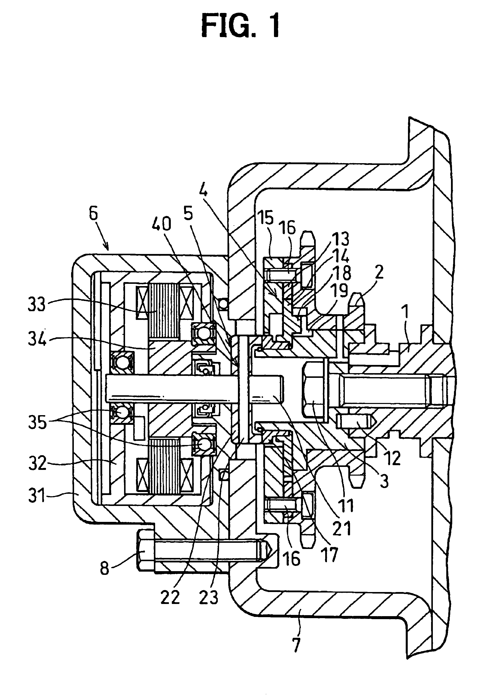
[0011]Referring to FIG. 1 through FIG. 3, the present invention is described hereinafter.

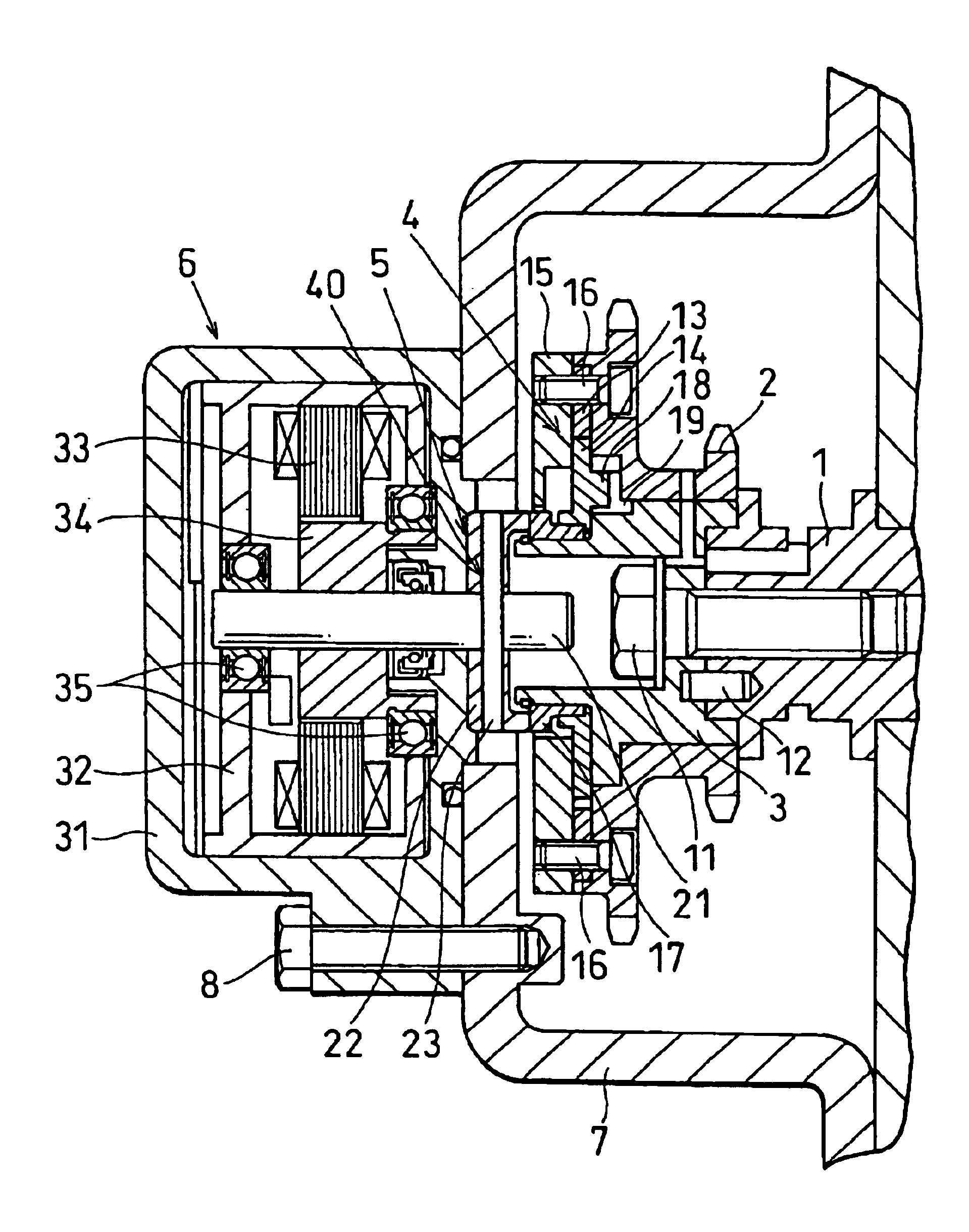
[0012]FIG. 1 shows the VVT controller of the embodiment. The VVT controller is connected with a cam shaft 1 of an engine (internal combustion engine:not shown) so that an opening-closing timing of an intake valve or an exhaust valve is varied continuously during engine operation. The left side in FIG. 1 is referred to the front side and the right side in FIG. 1 is referred to the rear side for convenience in explaining the embodiment.

[0013]The VVT controller is comprised of a sprocket 2 which is correspond to an input member of the invention, a cam connecting member 3 which is correspond to an output member of the invention, a phase converter 4 for the sprocket 2 and the cam connecting member 3, a coupling 5, an electric motor 6 and the like. As shown in FIG. 1, the sprocket 2, the cam connecting member 3, the phase converter 4 and the coupling 5 are assembled integrally and disposed in a chain ...

second embodiment

[0033]the present invention is described hereinafter.

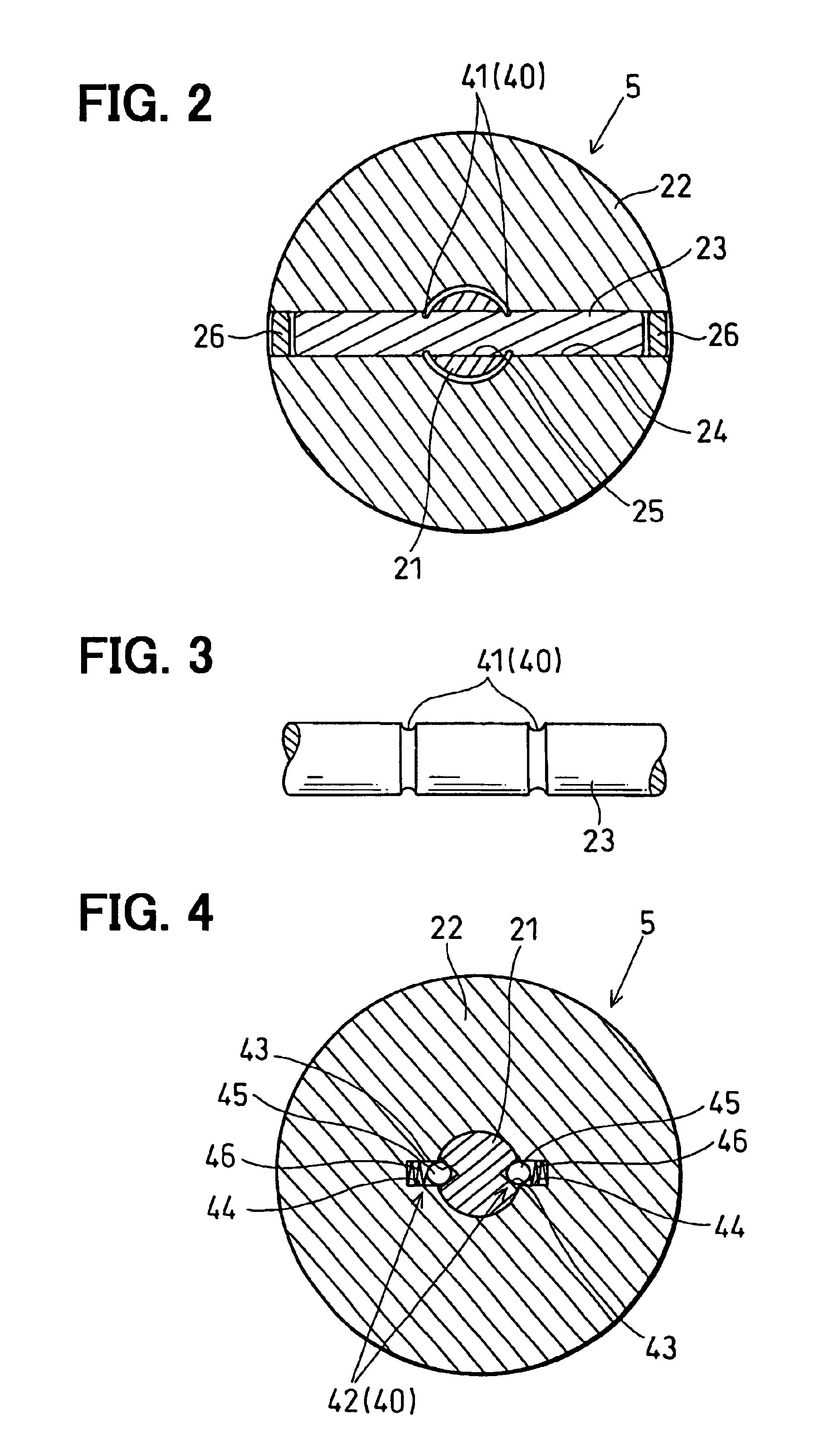
[0034]FIG. 4 shows the coupling 5 and the safety mechanism 40 of the second embodiment.

[0035]The safety mechanism 40 is disposed between the motor shaft 21 and the union 22 and is comprised of a clutch mechanism 42 which disconnect the motor shaft 21 from the union 22.

[0036]As shown in FIG. 4, the clutch mechanism 42 is comprised of a V-shaped outer hole 43 on the surface of the motor shaft 21, an inner hole 44 at inner peripheral of the union 22 with confronting to the outer hole 43, a ball 45 engaging with the outer hole 43 and inner hole 44 and a spring 46 biasing the ball 43 toward the outer hole 43.

[0037]A diameter of the ball 43 is larger than the depth of the outer hole 43. The half of the ball 43 extends off the outer hole 43 and engages the inner hole 44. The diameter of the inner hole 44 is large enough to accept the half of the ball 43 biased by the spring 46.

[0038]When some trouble is happened in the electric motor 6 a...


PUM


Abstract

The variable valve timing controller has an electric motor which rotates a phase converter. When the electric motor is locked for some reason, the over-load more than the predetermined value is applied to a motor shaft and the phase converter. In such a case, a pin connecting the motor shaft with the phase converter is sheared at a notch. Thus, a cam shaft and the phase converter were not locked, and breakage of a motor housing is prevented.

Description

CROSS REFERENCE TO RELATED APPLICATION[0001]This application is based on Japanese Patent Application No. 2003-59727 filed on Mar. 06, 2003, the disclosure of which is incorporated herein by reference.FIELD OF THE INVENTION[0002]The present invention relates to a protection method and a protection apparatus for an engine having a variable valve timing controller. The variable valve-timing controller is referred to as a VVT controller hereinafter.BACKGROUND OF THE INVENTION[0003]JP-A-11-153008 shows a VVT controller which is driven by an electric motor. In this VVT controller, a sun gear of a planetary gearing is rotated by the electric motor, thereby a phase between a ring gear and a carrier is varied. The planetary gearing functions as a phase converter. The ring gear is driven by a driving shaft of an engine and the carrier is connected with a cam shaft. The ring gear is referred to an input member and the carrier is referred to an output member in this invention.[0004]In this kind...

Claims


Application Information

Patent Timeline
IPC IPC(8): H02K7/10H02K7/108H02K7/00F01L1/46F01L1/34
CPCH02K7/003H02K7/108
Inventor IDO, SHINSUKETSUNODA, AKIRAMATSUURA, TOSHIHIROTAKABE, YOSHIYUKI
Owner DENSO CORP
Why Eureka
Try Eureka