Operator support pad for a vehicle

a technology for operating platforms and knee pads, which is applied in the direction of tractors, carriages/perambulators with multiple axes, transportation and packaging, etc. it can solve the problems of prior art pad deformation in an unacceptable manner and cracking of the outer skin of such knee pads

Inactive Publication Date: 2005-09-27
CROWN EQUIP CORP
View PDF19 Cites 35 Cited by
  • Summary
  • Abstract
  • Description
  • Claims
  • Application Information

AI Technical Summary

Problems solved by technology

It was found that the outer skin on such a kneepad would crack and tear over time allowing foam material beneath it to break away from the remaining portion of the pad.
Hence, this prior art pad degraded in an unacceptable manner over time.

Method used


Image

  • Operator support pad for a vehicle
  • Operator support pad for a vehicle
  • Operator support pad for a vehicle

Examples


Embodiment Construction

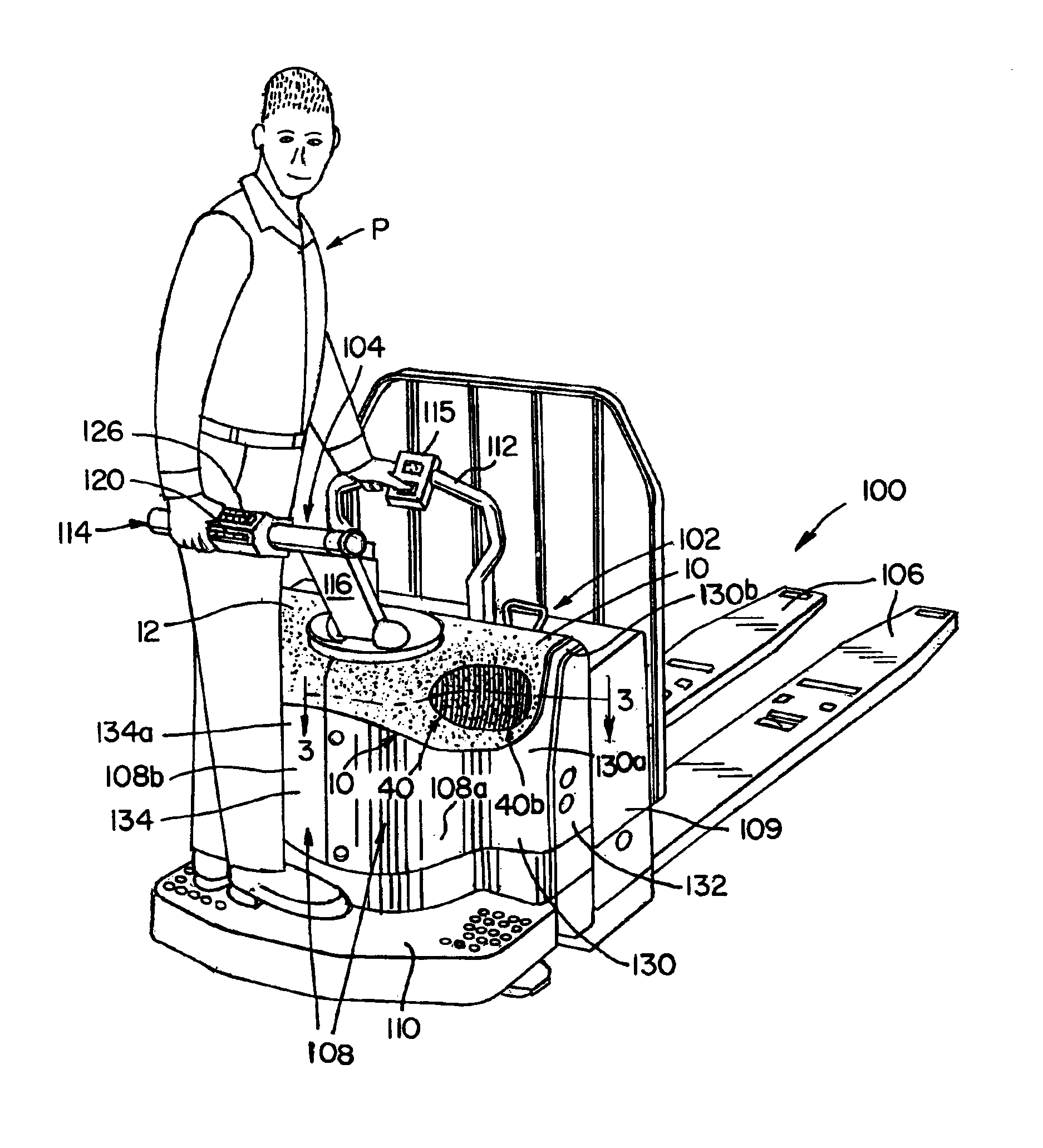
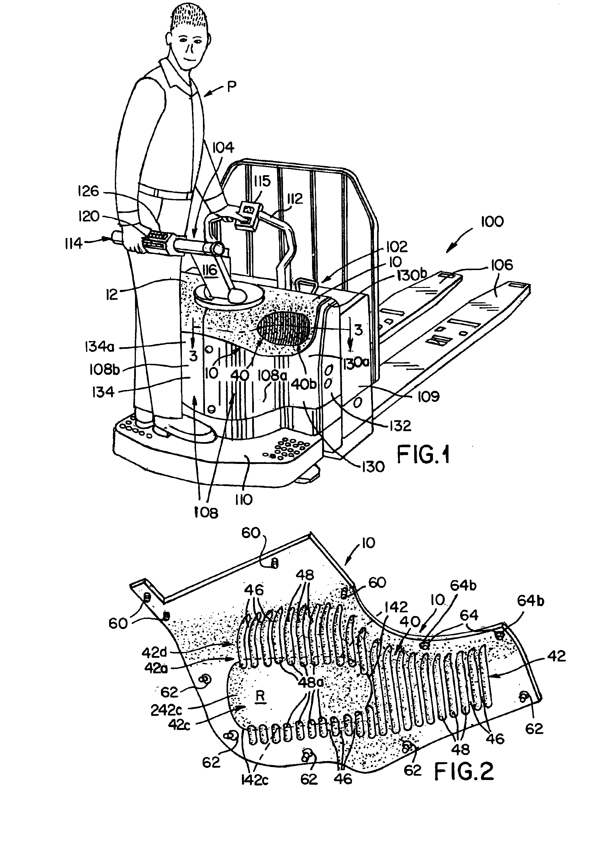
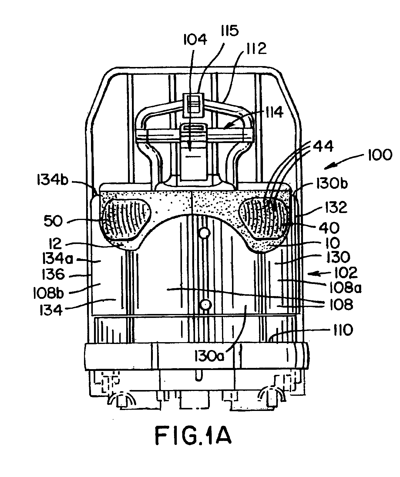
[0039]FIGS. 1, 1A and 1B illustrate a walkie / rider pallet truck 100 including first and second shrouds 10 and 12 formed in accordance with the present invention. As will be discussed further below, the shrouds 10, 12 function to insulate an operator P from thermal and acoustic energy generated by the truck 100. The shrouds 10, 12 further function to provide cushioning to an operator's knee as the operator P leans against one of the shrouds 10, 12 during vehicle operation.

[0040]The truck 100 includes a power unit 102, a steering control unit 104, and load carrying forks 106 that extend rearwardly from the power unit 102. The power unit 102 contains a steerable wheel (not shown), usually located directly beneath the steering control unit 104, a metal main casing 108 housing drive apparatus such as an electric traction motor (not shown), and an electric storage battery 109 mounted in front of the casing 108. The power unit 102 also includes a platform 110 onto which the operator P may ...


PUM


Abstract

A pallet truck has a power unit including a main casing for housing drive apparatus and a platform onto which an operator may step and ride while controlling the truck. The casing includes at least one substantially rigid wall member and an operator support pad associated with the wall member. The support pad includes a main body having first and second ribbed portions with the first portion defining a deformable pocket.

Description

BACKGROUND OF THE INVENTION[0001]The present invention relates to an operator support pad for a vehicle and, more particularly, to an operator support pad for use on a power unit of a rider pallet truck.[0002]Walkie / rider pallet trucks are known in the prior art, see U.S. Pat. Nos. 6,464,025 and 5,245,144, the disclosures of which are incorporated herein by reference. Such a truck comprises a power unit, a steering control unit and load carrying forks. The power unit comprises a metal casing containing a traction motor. The power unit may also comprise an electric storage battery. Surrounding a portion of the power unit casing is a platform onto which an operator may step and ride while controlling the truck. A wraparound knee pad, illustrated in FIG. 1 of the '025 patent, is provided on the power unit casing for providing a surface against which an operator may rest his / her knee during travel. The knee pad comprises a molded foam polyurethane pad having a substantially planar outer...

Claims


Application Information

Patent Timeline
Patent Type & Authority Patents(United States)
IPC IPC(8): B62D51/02B62D51/00B62B3/04B62B3/06B62B5/08B62B5/00B60R99/00
CPCB62B3/0612B62D51/02B62B5/087
Inventor GALLAGHER, MICHAEL P.HENSHAW, ROBERT J.
Owner CROWN EQUIP CORP
Why Eureka
Try Eureka