Illuminated electric part capable of efficiently receiving incident light from light source in light-transmissive manipulating shaft

a technology of incident light and illumination electric parts, which is applied in the direction of lighting and heating equipment, instruments, machines/engines, etc., can solve the problem of increasing the quantity of power consumption

Active Publication Date: 2005-09-27
ALPS ALPINE CO LTD
View PDF2 Cites 22 Cited by
  • Summary
  • Abstract
  • Description
  • Claims
  • Application Information

AI Technical Summary

Benefits of technology

[0022]Due to such a constitution, even when the manipulating shaft is rotatably and tiltably manipulated, it is possible to make the light from the light source efficiently incident inside the light-transmissive manipulating shaft.

Problems solved by technology

Accordingly, there arises a drawback that when a light emitting quantity is increased to ensure the sufficient intensity of illumination, a power consumption quantity is increased.

Method used


Image

  • Illuminated electric part capable of efficiently receiving incident light from light source in light-transmissive manipulating shaft
  • Illuminated electric part capable of efficiently receiving incident light from light source in light-transmissive manipulating shaft
  • Illuminated electric part capable of efficiently receiving incident light from light source in light-transmissive manipulating shaft

Examples


Embodiment Construction

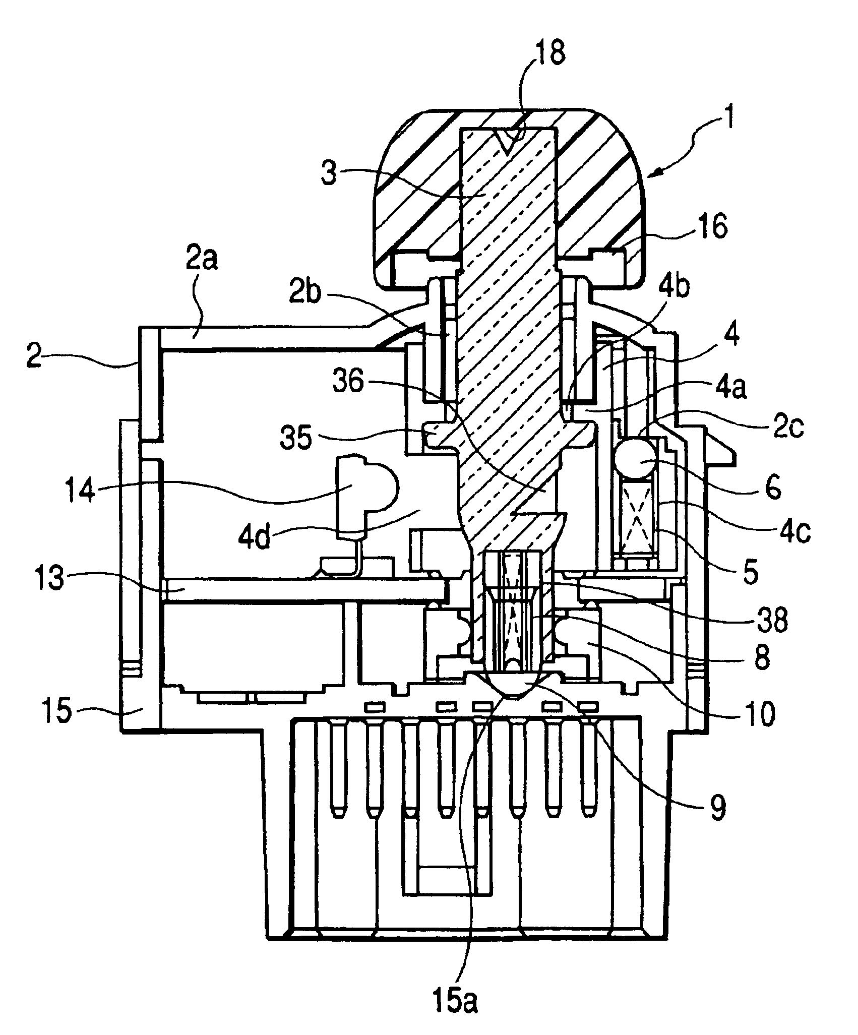
[0039]One embodiment of an illuminated electric part according to the present invention is explained in conjunction with FIG. 1 to FIG. 6.

[0040]The illuminated electric part according to this embodiment is explained in conjunction with an illuminated electric part which is applied to power mirror devices which electrically perform the adjustment of viewing angles of side mirrors which are provided at left and right sides of a car body of an automobile. The power mirror device is explained in conjunction with a type of device which manipulates a mirror selection switch for selecting either one of left and right side mirrors and a viewing angle adjusting switch for adjusting the viewing angle of the selected side mirror by the switch using a single manipulating shaft.

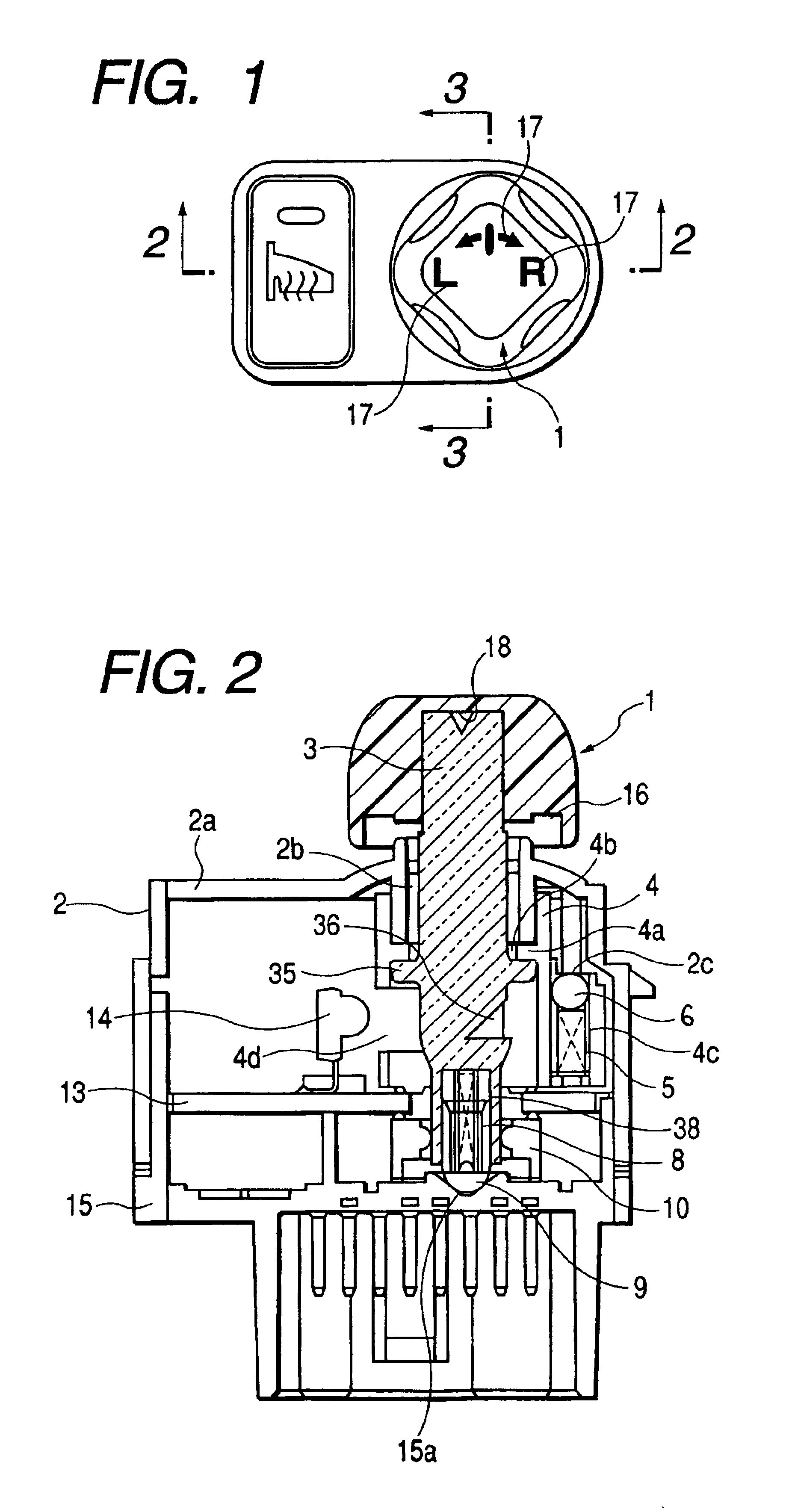
[0041]As can be clearly understood from FIG. 1 and FIG. 2, the illuminated electric part according to this embodiment is substantially constituted of a knob 1, a casing 2, a manipulating shaft 3, a movable bearing 4 which...


PUM


Abstract

An illuminated electric part includes a manipulating shaft which is rotatable and is stable at least at two points. The manipulating shaft is light-transmissive and includes a pictograph portion which is illuminated at a top portion thereof. The illuminated electric part includes a light emitting element which is arranged at a side of the manipulating shaft. The manipulating shaft includes side faces which constitute light incident faces in directions orthogonal to an optical path from the light emitting element at respective stable points and, at the same time, includes a conical light reflecting face having a downwardly extending top at a side opposite to the incident faces.

Description

BACKGROUND OF THE INVENTION[0001]1. Field of the Invention[0002]The present invention relates to an illuminated electric part which is served for a vehicle-mounted power mirror device or the like and is provided with a manipulating shaft which has an illuminated display on a top portion thereof.[0003]2. Description of the Related Art[0004]As this type of illuminated electric part, there has been known a switch having an illuminated knob which is described in Patent Reference 1.[0005]FIG. 7 is an exploded perspective view of this conventional switch having an illuminated knob. In the drawing, numeral 121 indicates a resin-made manipulating knob provided with a manipulating portion 121A and a fitting portion 121B, numeral 122 indicates a transparent circular-columnar or elliptical-columnar columnar first light guide body which is fitted in a center of the manipulating knob 121, and numeral 103 indicates a plate which is mounted on an illuminated face 122A formed on a front end of the ...

Claims


Application Information

Patent Timeline
Patent Type & Authority Patents(United States)
IPC IPC(8): G01D11/28B60R5/04H01H9/16H01H19/02H01H25/00H01H25/04
CPCG01D11/28
Inventor MIWA, TOSHITAKA
Owner ALPS ALPINE CO LTD
Why Eureka
Try Eureka