Mechanical timepiece

a mechanical timepiece and time-piece technology, applied in the direction of mechanical time indication, clock driving mechanism, instruments, etc., can solve the problems of not being able to house devices in watches, affecting the isochronism of the hairspring, and not being constan

Active Publication Date: 2005-09-27
MONTRES JOURNE
View PDF9 Cites 13 Cited by
  • Summary
  • Abstract
  • Description
  • Claims
  • Application Information

AI Technical Summary

Benefits of technology

[0009]The object of the present invention is to bring a solution to the problem of transmitting the force from the barrel s

Problems solved by technology

Consequently, the force transmitted by the escapement to the hairspring is not constant and the amplitude of the balance wheel varies, affecting its isochronism.
Moreover, these devices are not designed to b

Method used


Image

  • Mechanical timepiece
  • Mechanical timepiece

Examples


Embodiment Construction

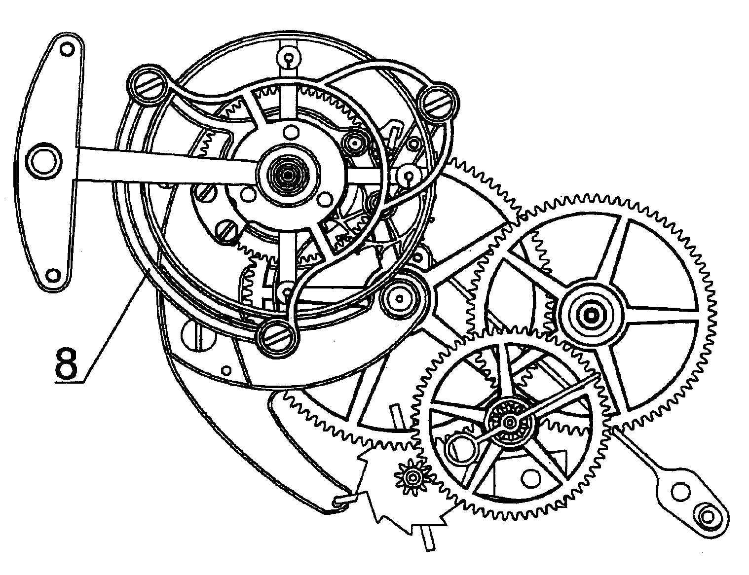
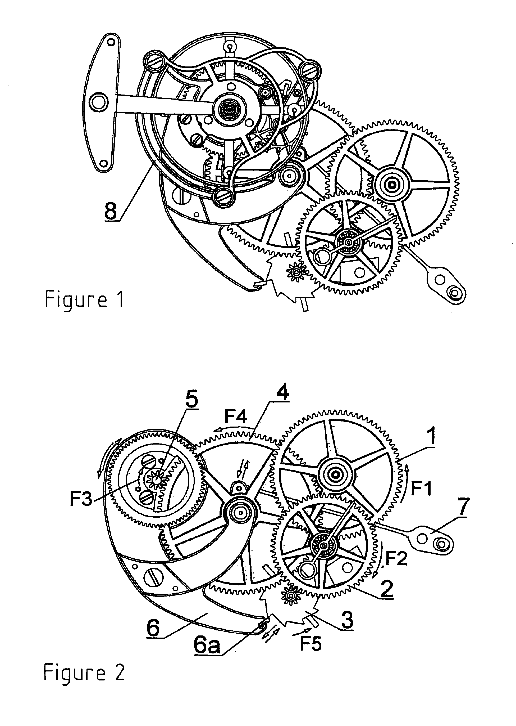
[0014]These figures show a part of the train of the timepiece. The first illustrated wheel of the customary train is the third wheel 1, the pinion of which meshes with the center wheel (not represented), itself provided with a pinion meshing with the toothing of the barrel containing the mainspring, as in all mechanical timepieces. This third wheel 1 is driven in the direction of the arrow F1 and meshes with the pinion of a first seconds wheel 2 turning in the opposite direction shown by the arrow F2.

[0015]The pinion of this first seconds wheel 2 meshes with a setting wheel 4, which itself meshes with the pinion of a second seconds wheel 5. In the embodiment illustrated by FIG. 1, the pivot pin of this second seconds wheel 5 is fixedly connected to a traditional tourbillion escapement 8, which there is no need to describe here insofar as it is not necessary to an understanding of the present invention. In another embodiment, the second seconds wheel 5 could mesh with the pinion of a...


PUM


Abstract

A storage device comprises a first seconds wheel, engaging with a mainspring, and a second seconds wheel, a setting wheel for connecting these two seconds wheels, a yoke on which said setting wheel is pivotably mounted, the pivot axis of this yoke and that of the second seconds wheel being coaxial, a stop wheel kinematically linked with said first seconds wheel, a finger fixedly connected to said yoke, a storage spring for exerting upon said yoke a force tending to separate said finger from said stop wheel, whereas the force exerted upon said setting wheel by said mainspring serves to press said finger against said stop wheel, so that the latter is wound to the point where a tooth of said stop wheel abuts against said finger.

Description

CROSS REFERENCE TO RELATED APPLICATIONS[0001]This application is claims priority of European Application No. 03405772.9 filed Oct. 28, 2003, which is included in its entirety by reference made hereto.BACKGROUND OF THE INVENTION[0002]1. Field of the Invention[0003]The present invention relates to a mechanical timepiece comprising an oscillator, the oscillating motion of which is maintained by a mainspring, in which a periodic energy storage device is disposed between this mainspring and an escapement associated with said oscillator.[0004]2. Description of Related Art[0005]The energy source for said mechanical timepieces is constituted by a mainspring constituted by a leaf spring wound in a barrel, its outer end being fixedly connected to the barrel drum, whereas its inner end is fixedly connected to the arbor of this barrel. Upon slackening, the mainspring drives the barrel drum. The latter has an external toothing engaging with the train of the timepiece, which toothing ends at the ...

Claims


Application Information

Patent Timeline
IPC IPC(8): G04B1/00G04B17/00G04B1/22G04B17/28
CPCG04B1/225G04B17/285
Inventor JOURNE, FRAN.CEDILLA.OIS-PAUL
Owner MONTRES JOURNE
Why Eureka
Try Eureka