
Method and apparatus for a multiple fin style current connector

a current connector and fin-style technology, applied in the direction of connection contact member material, non-rotary current collector, coupling device connection, etc., can solve the problems of electrical connection wear, electrical conductor movement independent of one another, electrical system connection, etc., and achieve the effect of increasing the overall size of the mlb assembly

Inactive Publication Date: 2005-09-27
SIEMENS ENERGY INC
View PDF9 Cites 14 Cited by
  • Summary
  • Abstract
  • Description
  • Claims
  • Application Information

AI Technical Summary

Benefits of technology

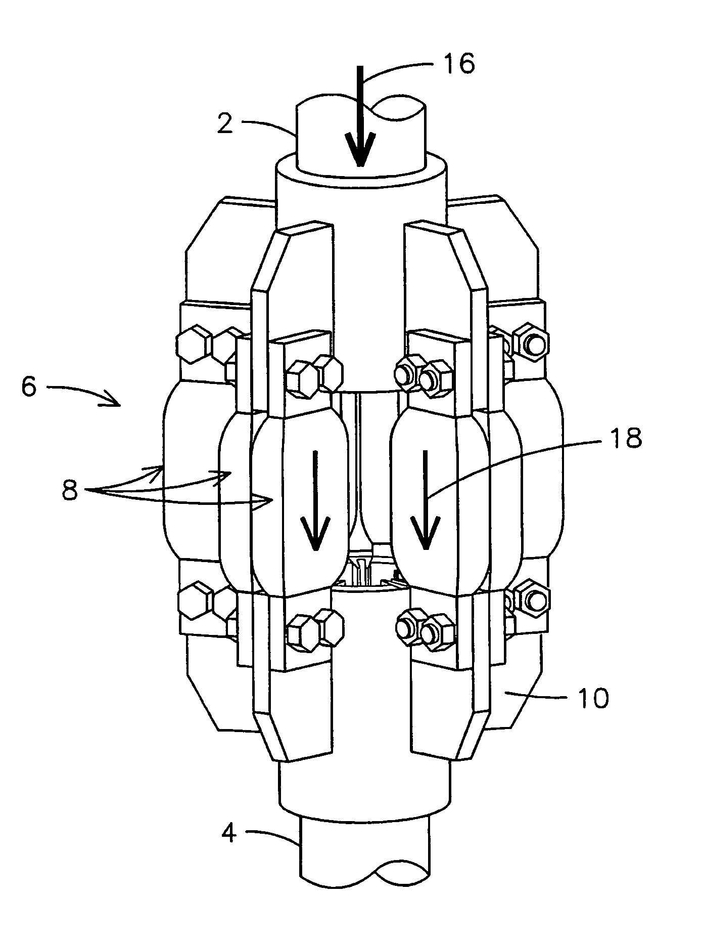
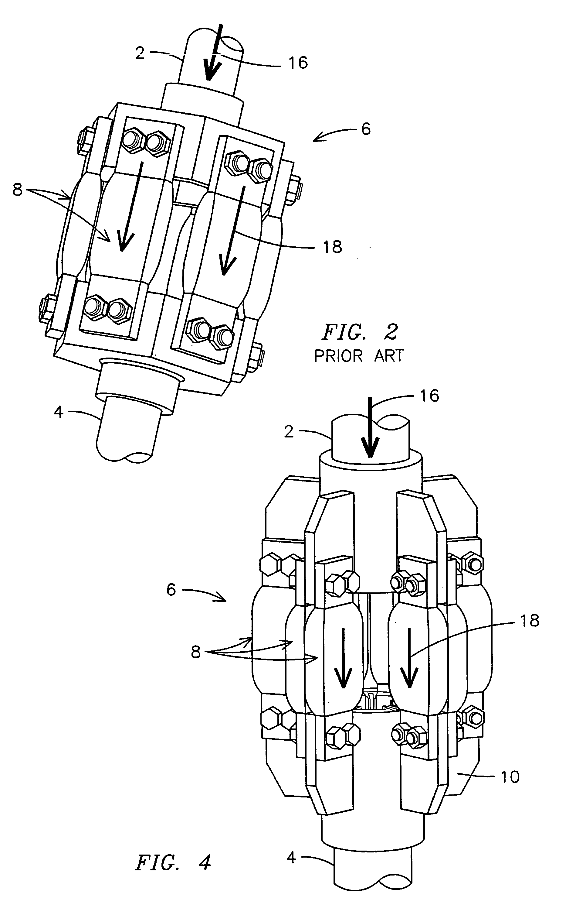
[0007]With the foregoing in mind, methods and apparatus consistent with the present invention facilitate the creation of a MLB assembly comprising two terminal ends of conductors that have a matching series of radially spaced fins, and conductive flexible connectors joining the matching fins together. Each matched fin may have one or two flexible connectors joining it to the matching fin. Unlike conventional approaches, such as linearly spaced, or radially spaced conductive flexible connectors, the present invention allows for even distribution of an electrical current across the multiple conductive flexible connectors, and also allows for the addition of a greater number of flexible connectors without significantly increasing the overall size of the MLB assembly.

Problems solved by technology

In large scale electrical conductors, such as those used in the power generation industry, there are inherent problems in connecting electrical systems.
One of the problems is that the electrical conductors will move independently of one another.
This is due to the large scale mechanisms experiencing a difference of temperature, vibration or other environmental factors.
If the connection point is rigid then the electrical connection wears rapidly and even breaks, which will cause shorts and other damage.
Therefore, the effective maximum current that this type of MLB assembly can carry is limited since increasing the number of flexible connectors 8 has a diminishing improvement on the current capacity of the MLB assembly.
Further, the flexible connectors on the outer edges of the MLB assembly wear proportionally faster than the other flexible connectors since they carry a greater burden of the electrical flow.
This reduces the life expectancy of the MLB assembly and creates potential safety issues.
This design, however, is still limited by the overall size restrictions of the MLB assembly.
In other words, the MLB assembly can only be so large before it creates problems with the system design.

Method used


Image

  • Method and apparatus for a multiple fin style current connector
  • Method and apparatus for a multiple fin style current connector
  • Method and apparatus for a multiple fin style current connector

Examples


Embodiment Construction

[0016]The present invention deals with MLB assemblies, and more particularly with MLB assemblies that have increased current flow capacity while maintaining even current through the flexible connector subcomponents. In the past, attempts have been made to either increase capacity or evenly distribute current, but so far the art has been unable to do both.

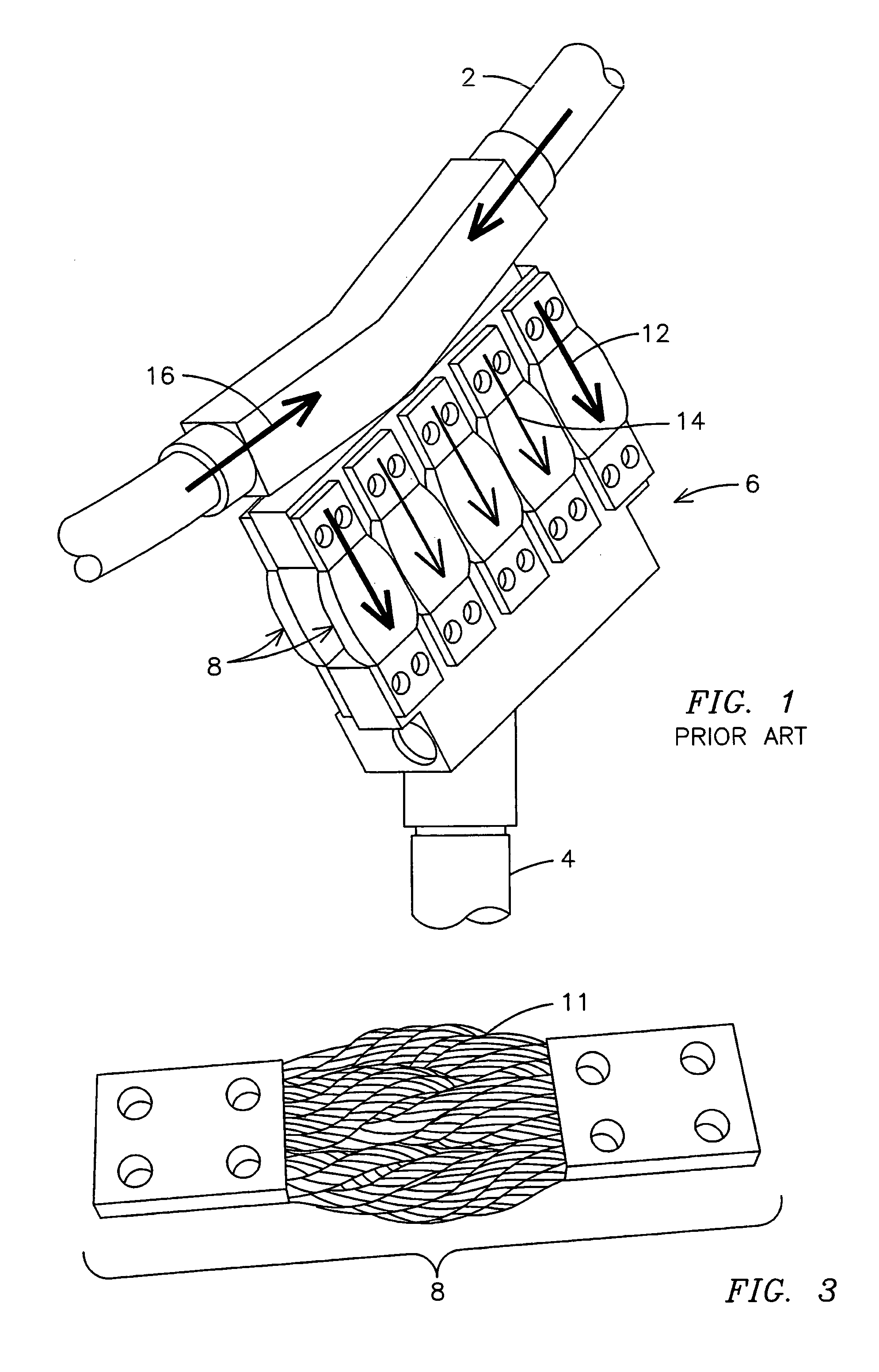
[0017]As shown in FIG. 1, the linearly placed flexible connectors 8 can carry a significant current 16, but the current tends to be carried on the outermost flexible connectors 12. This causes the outermost flexible connectors 12 to wear considerably faster than the inner flexible connectors 14. Also, since the current 16 tends to carry to the periphery, the addition of more flexible connectors 8 has a diminishing return on the net gain of current flow capacity.

[0018]The MLB assembly 6 shown in FIG. 2 effectively spreads the current flow 16 evenly 18 among the component flexible connectors 8. This arrangement, however, tends to have...


PUM


Abstract

In one embodiment the present invention is an MLB assembly 6 that is made up of two circular terminal conductor ends 2, 4. Multiple fins 10 radially extend from each of the two circular terminal conductor ends 2, 4, and each fin on each of the two circular terminal conductor ends has a matching fin on the other of the two circular terminal ends. Multiple flexible connectors 8 are attached to the fins 10 that electrically connects the terminal conductors 2, 4. The flexible connectors 8 also allow for a difference of movement between the two circular terminal ends. Current flowing through the MBL assembly 16 is evenly distributed 18 through the plurality of flexible connectors.

Description

FIELD OF THE INVENTION[0001]The present invention relates to methods and apparatus for increasing the current capacity of a main lead to braid (MLB) assembly, while maintaining an even distribution of current across the flexible connector sub components. The MLB assembly comprises two terminal ends of conductors that have a matching series of radially spaced fins, and conductive flexible connectors joining the matching fins together.BACKGROUND[0002]In large scale electrical conductors, such as those used in the power generation industry, there are inherent problems in connecting electrical systems. One of the problems is that the electrical conductors will move independently of one another. This is due to the large scale mechanisms experiencing a difference of temperature, vibration or other environmental factors. If the connection point is rigid then the electrical connection wears rapidly and even breaks, which will cause shorts and other damage.[0003]MLB assemblies have therefore...

Claims


Application Information

Patent Timeline
IPC IPC(8): H01R41/00H01R4/30
CPCH01R4/30H01R4/302H02G5/10H01R4/60H02G5/002H02K3/505H01R35/02H01R11/01H01R35/04
Inventor KOGAN, VIKTORWOOSLEY, SEANWARD, ROBERT ALAN
Owner SIEMENS ENERGY INC
Learn More