Hood mounting

a technology for hoods and hoods, applied in the field of protective hoods, can solve the problems of high manufacturing cost and slight sticking, and achieve the effect of simple construction and easy installation and removal

Active Publication Date: 2005-09-27
HILTI AG
View PDF10 Cites 64 Cited by
  • Summary
  • Abstract
  • Description
  • Claims
  • Application Information

AI Technical Summary

Benefits of technology

[0005]The object of the present invention is to eliminate the aforementioned drawbacks in a protective hood arrangement on a tool machine and to provide easy installation and removal by virtue of a simple construction.

Problems solved by technology

The drawback in the prior art protective hood arrangement is that the features for the optional fixing of the protective hood in different locking positions are relatively expensive and consequently result in high costs of manufacture.
At the same time, this precise matching of the receiving groove to the dimensions of the brackets results in a slight sticking, particularly when the brackets are slightly bent.
This can result in a misalignment of the protective hood into a new locking position or can result in substantial problems at the time of their installation or dismantling.

Method used


Image

  • Hood mounting
  • Hood mounting
  • Hood mounting

Examples


Embodiment Construction

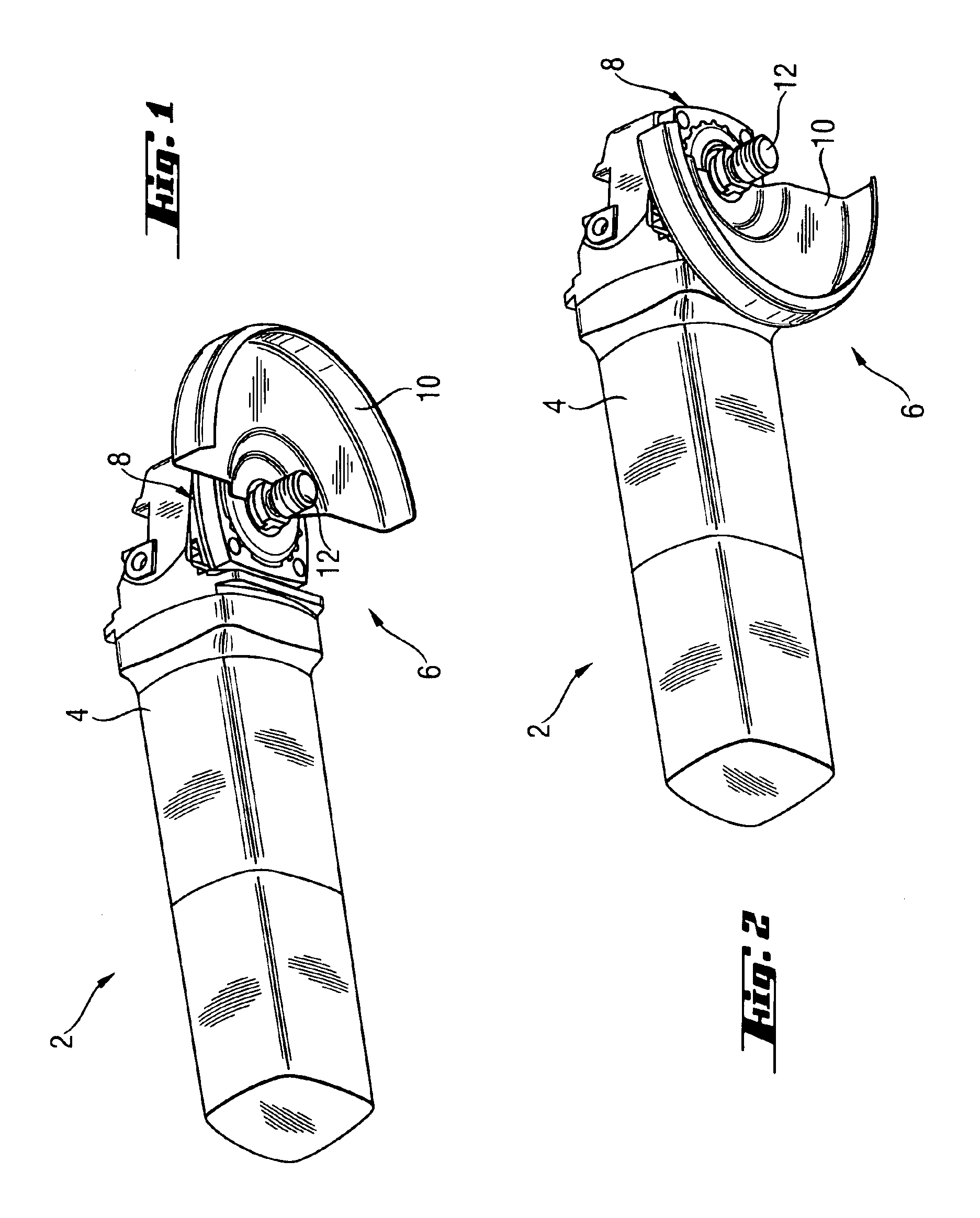
[0026]FIG. 1 represents a tool machine 2 in the form of an angle grinder having a housing 4, on whose tool side end a protective hood assembly—overall represented by 6—is provided. The protective hood assembly 6 consists essentially of a securing unit 8 connected securely with the housing 4, at which a protective hood 10 is removably fastened without the aid of tools.

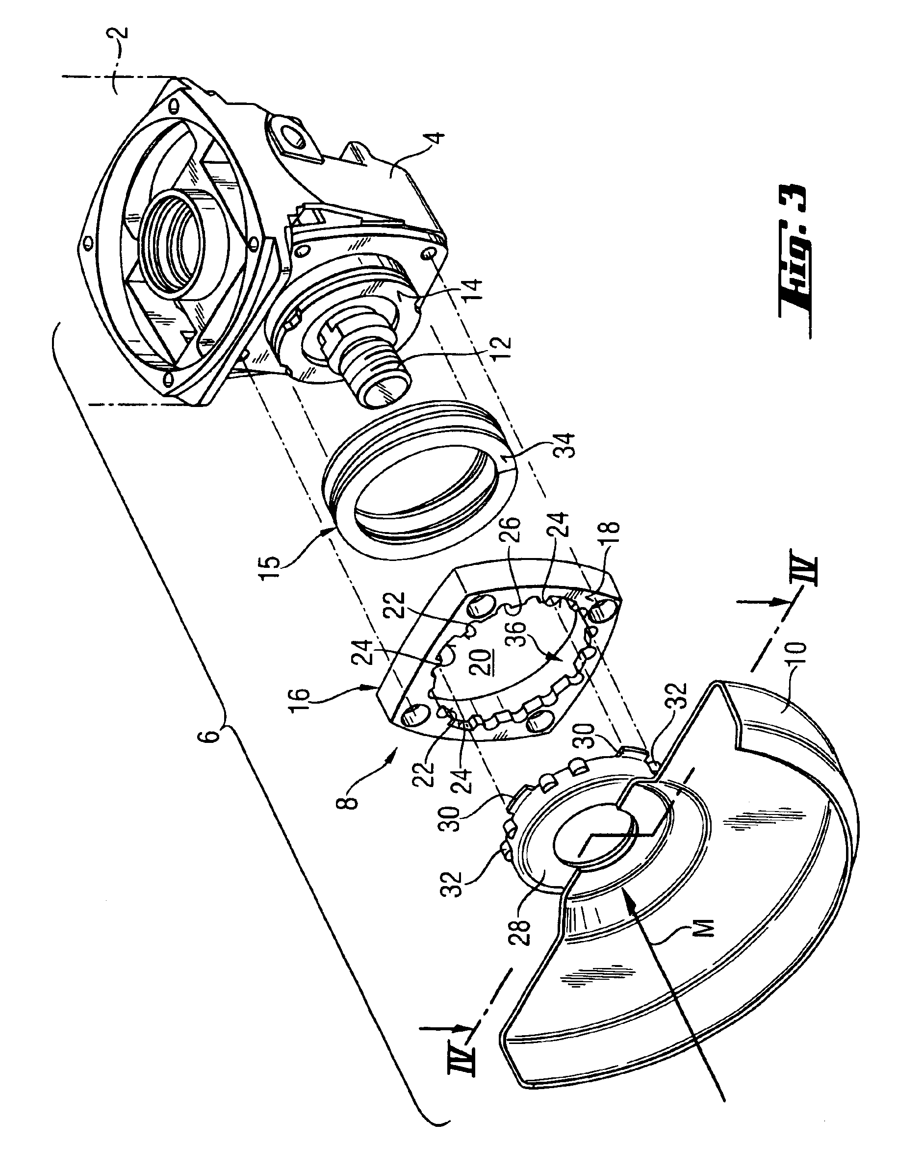
[0027]As represented in FIG. 1 in conjunction with FIG. 2, the protective hood can be rotated relative to the housing 4 of the tool machine into different locking positions. The structure of the protective hood assembly 6 provided for this purpose can be seen in FIG. 3.

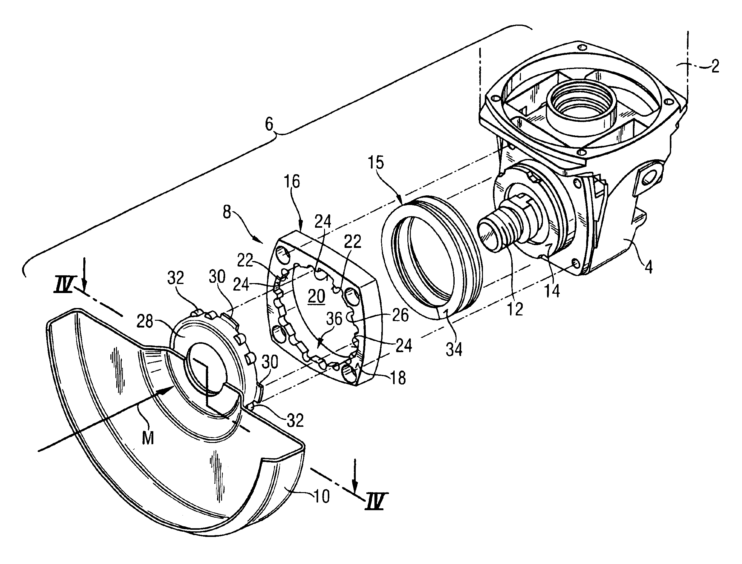
[0028]The securing assembly 8 of the protective hood arrangement 6 represented in an exploded view in FIG. 3 has, around a tool receptacle 12, which is used for attachment of a tool (not shown), such as in particular a cutting or grinding disk, a substantially annular fastening flange 14 fixedly attached to the housing. A cylindrical helical spring 15 is ...


PUM

PropertyMeasurementUnit
of rotationaaaaaaaaaa
spring forceaaaaaaaaaa
outer radiusaaaaaaaaaa

Abstract

A protective hood assembly (6) for a tool machine (2) is formed of a housing with a protective hood (10), to a securing assembly (8, 8′, 8″) relative to the housing (4) in different rotary positions, wherein at least one lock-in part (30, 30′) is provided, which can be brought along a direction of installation (M) into a receiving region (36) of a locking housing (16) of the securing assembly (8) and at which, by rotating, can be brought into a bayonet-like engagement and wherein locking means (32, 32′) are provided on the protective hood, the locking means being capable of being locked in different locking positions with counter locking means (26, 26′) of the securing assembly (8). The receiving region (36) is limited on a side facing the housing (4) at least in part by an abutting wall (34, 34′, 34ä, 34″b), which is mobile.

Description

[0001]The invention relates to a protective hood for a tool machine, in particular an angle grinding machine, including a housing with a protective hood, which can be attached on a fastening assembly in different rotary positions relative to the housing, for example, at least one lock-in part is provided, which can be brought in a installation direction into a receiving zone, formed in a securing assembly and can be brought into a bayonet-type connection by rotating it and whereby the protective hood is provided with a locking means, which can be locked in different locking positions using counter-locking means of the securing assembly.BACKGROUND OF THE INVENTION[0002]This type of protective hoods have the advantage that the protective hood is installed and removed on the tool machine without the use of tools. In addition, the protective hood in the secured condition, depending on need, can be brought, relative to the tool machine, also without the use of tools from one locked posit...

Claims


Application Information

Patent Timeline
Patent Type & Authority Patents(United States)
IPC IPC(8): B23D47/00B24B23/00B24B55/05B24B55/00B24B55/04B24B23/02
CPCB24B23/02B24B55/052
Inventor KOSCHEL, CHRISTIANHARTMANN, MARKUS
Owner HILTI AG
Why Eureka
Try Eureka