Deformation reduction at the main chamber

a vacuum chamber and deformation reduction technology, applied in the field of vacuum chambers, can solve the problems of large covers being more susceptible to deformation under vacuum load, affecting the performance of vacuum chambers, and affecting the quality of vacuum chambers

Inactive Publication Date: 2005-09-27
LAM RES CORP
View PDF8 Cites 245 Cited by
  • Summary
  • Abstract
  • Description
  • Claims
  • Application Information

AI Technical Summary

Problems solved by technology

If the upper electrode 26 or some other critical element fastened to more than one point on the cover is brittle, the deformation may crack the upper electrode or other critical element.
Wider diameters of t

Method used


Image

  • Deformation reduction at the main chamber
  • Deformation reduction at the main chamber
  • Deformation reduction at the main chamber

Examples


Embodiment Construction

[0014]The present invention will now be described in detail with reference to a few preferred embodiments thereof as illustrated in the accompanying drawings. In the following description, numerous specific details are set forth in order to provide a thorough understanding of the present invention. It will be apparent, however, to one skilled in the art, that the present invention may be practiced without some or all of these specific details. In other instances, well known process steps and / or structures have not been described in detail in order to not unnecessarily obscure the present invention.

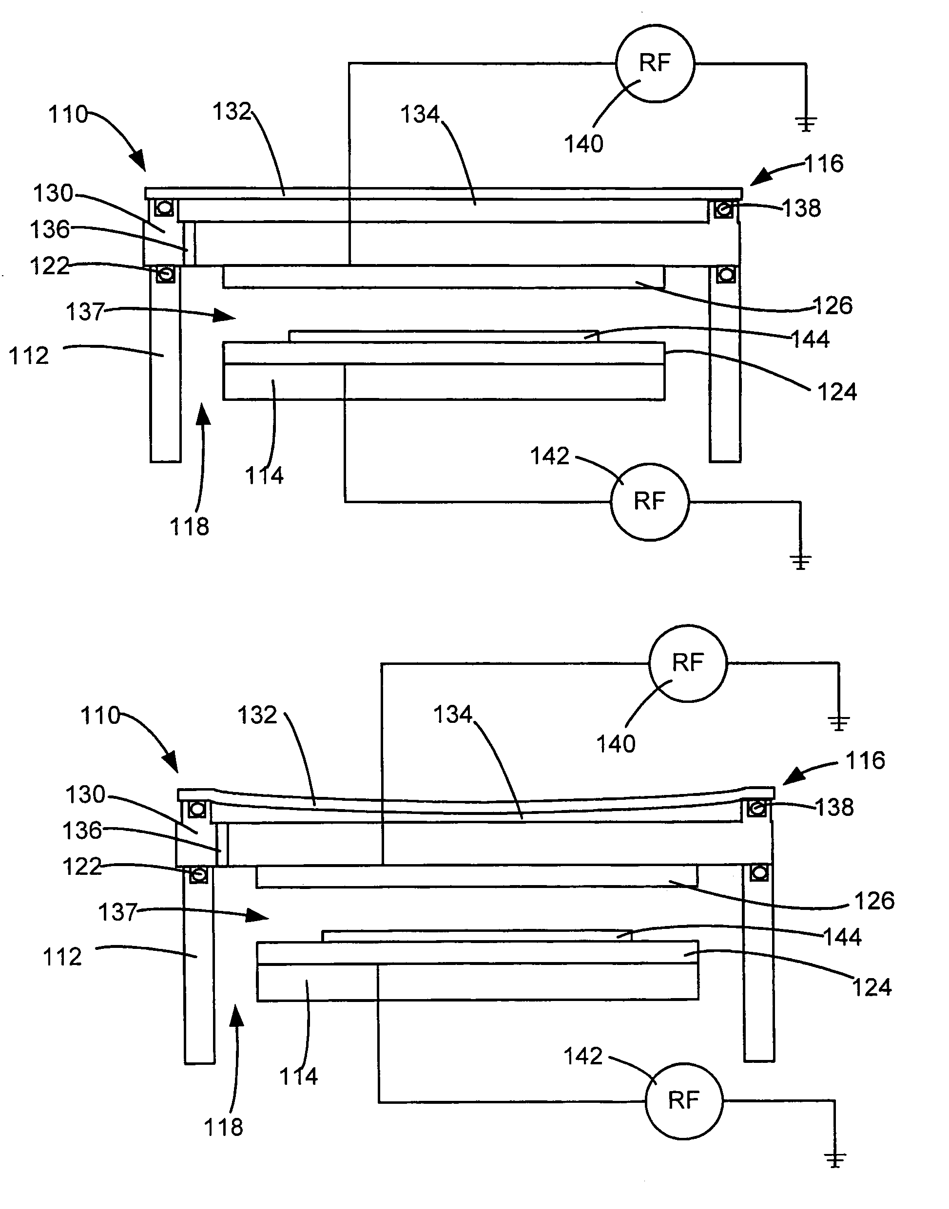
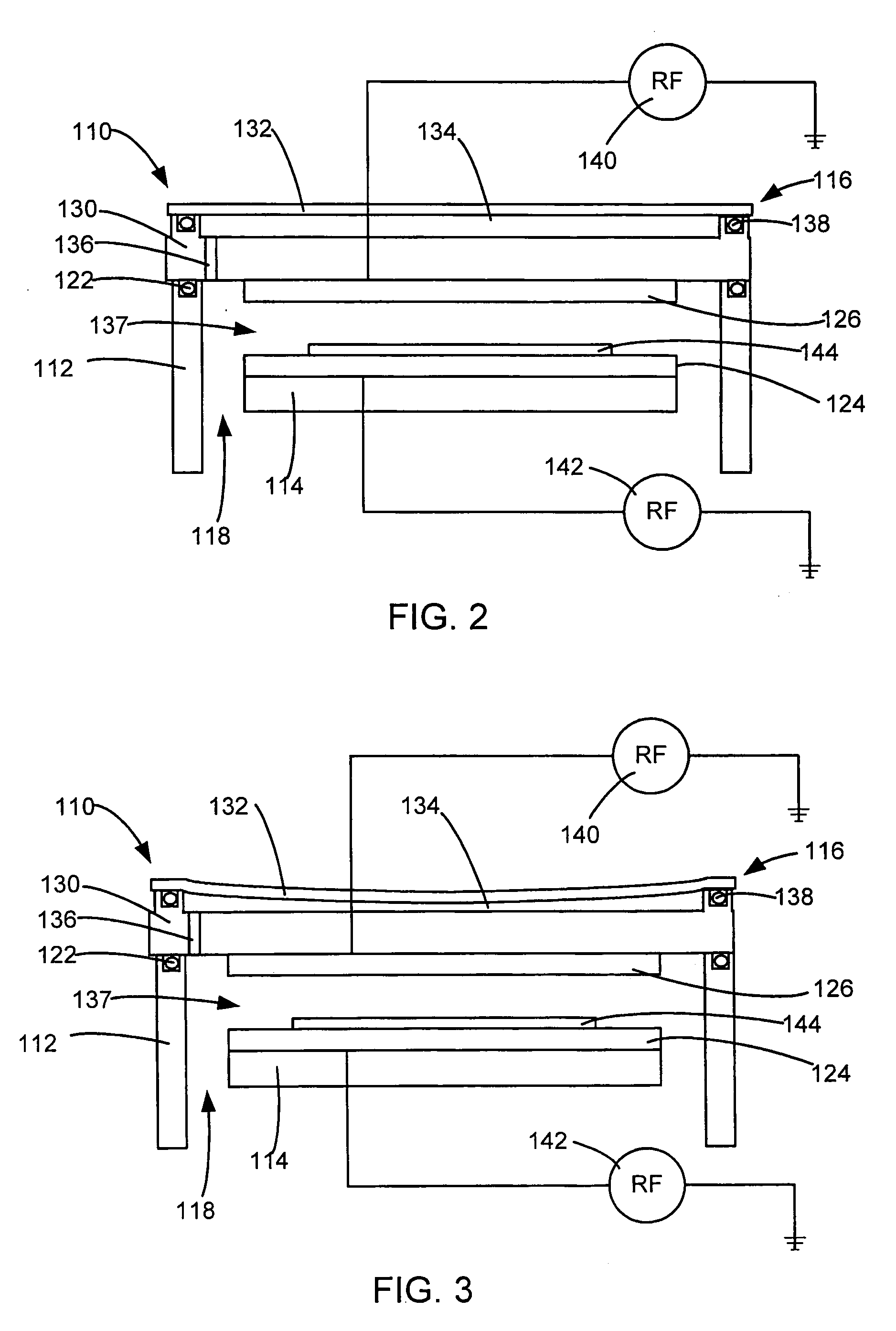
[0015]To facilitate discussion, FIG. 2 is a schematic view of a vacuum chamber 110 according to one embodiment of the invention. The vacuum chamber 110 may have a chamber wall 112, a bottom 114, a cover 116 and at least one exhaust port 118 to remove gas from the vacuum chamber to maintain a vacuum. The chamber wall 112 defines an opening. The cover 116 extends across the opening. The cove...


PUM

PropertyMeasurementUnit
Poweraaaaaaaaaa
Deformation enthalpyaaaaaaaaaa

Abstract

A vacuum chamber with a cover with a first section, a second section, and a pocket between the first section and second section is provided. The vacuum chamber has a main cavity to which the first section is adjacent. The vacuum chamber may be used for plasma processing, which may require a critical element to be supported by the first section. The pocket is in fluid communication with the main cavity. When a vacuum is created in the main cavity, the pressure is also reduced in the pocket. As a result, the second section of the cover is deformed by the vacuum in the pocket. However, the vacuum in the pocket helps to prevent the first section from deforming, providing better support for the critical element.

Description

RELATED APPLICATIONS[0001]This is a Divisional application of prior U.S. application Ser. No. 09 / 634,806, entitled “DEFORMATION REDUCTION AT THE MAIN CHAMBER”, filed on Aug. 8, 2000, now U.S. Pat. No. 6,712,929 which is incorporated herein by reference and from which priority under 35 U.S.C. § 120 is claimed.BACKGROUND OF THE INVENTION[0002]The present invention relates to vacuum chambers. More particularly, the present invention relates to an improved vacuum chamber in a plasma processing device.[0003]Vacuum chambers may be used in manufacturing. Vacuum chambers may be used for plasma processing.[0004]To facilitate discussion, FIG. 1 is a schematic view of a prior art vacuum chamber 10 used in a plasma processing process. The vacuum chamber 10 may have a chamber wall 12, a bottom 14, a cover 16 and at least one exhaust port 18 to remove gas from the vacuum chamber to maintain a vacuum. The cover 16 may be mounted on the chamber wall 12 with a seal 22 between the cover 16 and the ch...

Claims


Application Information

Patent Timeline
IPC IPC(8): H01J37/32H01L21/00
CPCH01J37/32458H01L21/67069
Inventor LENZ, ERICELLINGBOE, ALBERT R.HAO, FANGLI
Owner LAM RES CORP
Why Eureka
Try Eureka