Film deposition apparatus, substrate processing apparatus, film deposition method, and storage medium

a film deposition apparatus and substrate technology, applied in chemical vapor deposition coatings, coatings, metallic material coating processes, etc., can solve the problems of difficult to achieve satisfactory ald (or mld) processes, long process time, and inability to apply the proposed film deposition technique to the proposed film deposition apparatus and the proposed film deposition method. , to achieve the effect of high throughpu

Active Publication Date: 2016-02-23
TOKYO ELECTRON LTD
View PDF151 Cites 285 Cited by
  • Summary
  • Abstract
  • Description
  • Claims
  • Application Information

AI Technical Summary

Benefits of technology

[0023]Accordingly, one aspect of the present invention is to provide a film deposition apparatus, a substrate processing apparatus, a film deposition method and a computer-readable storage medium, which can obtain a high throughput, perform a satisfactory process by preventing a plurality of reaction gases from becoming mixed on a substrate, and protect a vacuum chamber from corrosion with respect to the reaction gases or a cleaning gas, when forming a thin film from a plurality of stacked layers of reaction products by sequentially supplying the plurality of reaction gases, which mutually react, to the surface of the substrate.
[0026]According to a third aspect of the present invention, there is provided a film deposition method for depositing a thin film on a substrate in a space surrounded by a vacuum chamber protection part which protects a vacuum chamber from corrosion by sequentially supplying at least two kinds of source gases, including a first reaction gas and a second reaction gas, and by carrying out a supply cycle to sequentially supply said at least two kinds of source gases, said film deposition method comprising placing a substrate on a turntable within the vacuum chamber; rotating the turntable; supplying, from a first reaction gas supply part, a first reaction gas to a first space formed between an upper surface of the turntable and a top plate of the vacuum chamber protection part; supplying, from a second reaction gas supply part disposed at a position different from a position of the first reaction gas supply part along a rotating direction of the turntable, a second reaction gas to a second space formed between the upper surface of the turntable and the top plate of the vacuum chamber protection part; supplying, from a first separation gas supply part disposed between the first reaction gas supply part and the second reaction gas supply part, a first separation gas to a third space formed between the upper surface of the turntable and the top plate of the vacuum chamber protection part, said third space being lower than the first space and the second space; supplying a second separation gas for separating the first reaction gas and the second reaction gas to a central part area under the top plate and above the turntable; and moving the substrate with a rotation of the turntable, to repeat supplying the first reaction gas to the surface of the substrate, stop supplying the first reaction gas, supplying the second reaction gas to the surface of the substrate, and stop supplying the second reaction gas, in order to exhaust the first reaction gas and the second reaction gas together with the first separation gas and the second separation gas, to thereby form a thin film on the substrate.
[0027]According to a fourth aspect of the present invention, there is provided a computer-readable storage medium which stores a program which, when executed by a computer, causes the computer to perform a film deposition process for depositing a thin film on a substrate in a space surrounded by a vacuum chamber protection part which protects a vacuum chamber from corrosion by sequentially supplying at least two kinds of source gases, including a first reaction gas and a second reaction gas, and by carrying out a supply cycle to sequentially supply said at least two kinds of source gases, said program comprising a procedure causing the computer to rotate a turntable having a substrate placed thereon; a procedure causing the computer to supply, from a first reaction gas supply part, a first reaction gas to a first space formed between an upper surface of the turntable and a top plate of the vacuum chamber protection part; a procedure causing the computer to supply, from a second reaction gas supply part disposed at a position different from a position of the first reaction gas supply part along a rotating direction of the turntable, a second reaction gas to a second space formed between the upper surface of the turntable and the top plate of the vacuum chamber protection part; a procedure causing the computer to supply, from a first separation gas supply part disposed between the first reaction gas supply part and the second reaction gas supply part, a first separation gas to a third space formed between the upper surface of the turntable and the top plate of the vacuum chamber protection part, said third space being lower than the first space and the second space; a procedure causing the computer to supply, a second separation gas for separating the first reaction gas and the second reaction gas to a central part area under the top plate and above the turntable; and a procedure causing the computer to move the substrate with a rotation of the turntable, and repeat supplying the first reaction gas to the surface of the substrate, stop supplying the first reaction gas, supplying the second reaction gas to the surface of the substrate, and stop supplying the second reaction gas, in order to exhaust the first reaction gas and the second reaction gas together with the first separation gas and the second separation gas, to thereby form a thin film on the substrate.

Problems solved by technology

When such a deposition chamber is used, it takes a long time for a purge gas to purge the reaction gases, resulting in an extremely long process time because the number of cycles may reach several hundred.
However, the following problems are encountered when a film deposition process is performed using the film deposition apparatus or the film deposition method proposed in the eight patent documents described above, by arranging a plurality of substrates on the turntable within the vacuum chamber in the rotating direction.
According to the film deposition apparatus and the film deposition method proposed in the Japanese Laid-Open Patent Publication No. 2001-254181, the air curtain generated from the purge gas nozzles cannot prevent mixture of the reaction gases and may allow the reaction gases on both sides particularly from the upstream side of the rotating direction to flow through the air curtain, because the wafer support member rotates.
If the first reaction gas and the second reaction gas mixed above the wafer, a reaction product is adsorbed on the wafer surface, and it becomes difficult to perform a satisfactory ALD (or MLD) process.
Accordingly, the film deposition technique employing the ALD cannot be applied to the proposed film deposition apparatus and the proposed film deposition method.
In addition, when the evacuation port is provided in a surface opposing the region where the wafer passes, the wafer is easily contaminated by the particles that are blown upwards from the susceptor surface.
As a result, a reaction product is generated in the purge gas compartment, which may cause particles to contaminate the wafer.

Method used


Image

  • Film deposition apparatus, substrate processing apparatus, film deposition method, and storage medium
  • Film deposition apparatus, substrate processing apparatus, film deposition method, and storage medium
  • Film deposition apparatus, substrate processing apparatus, film deposition method, and storage medium

Examples


first embodiment

[0052]A description will be given of a film deposition apparatus and a film deposition method in a first embodiment of the present invention, by referring to FIGS. 1 through 10.

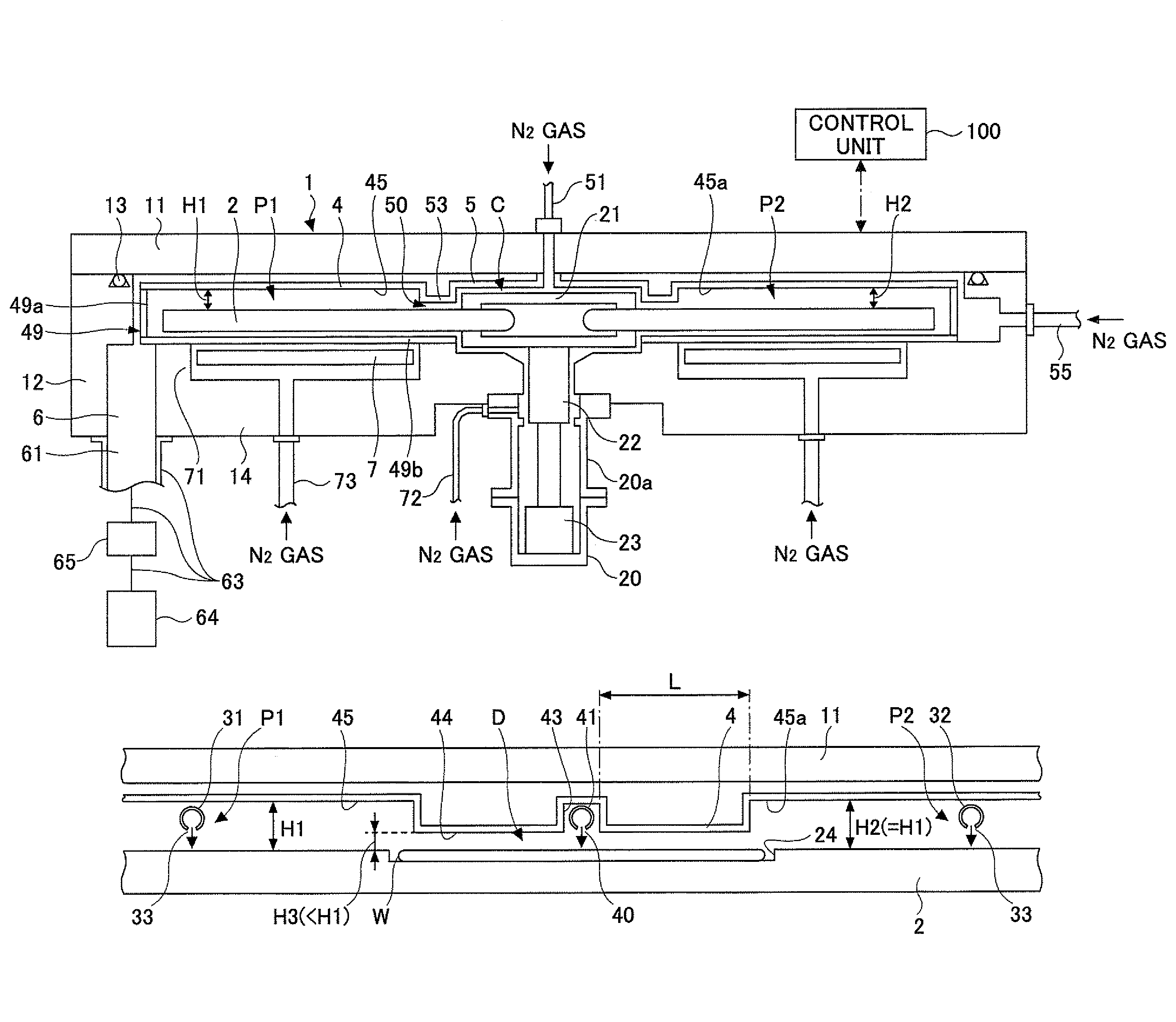
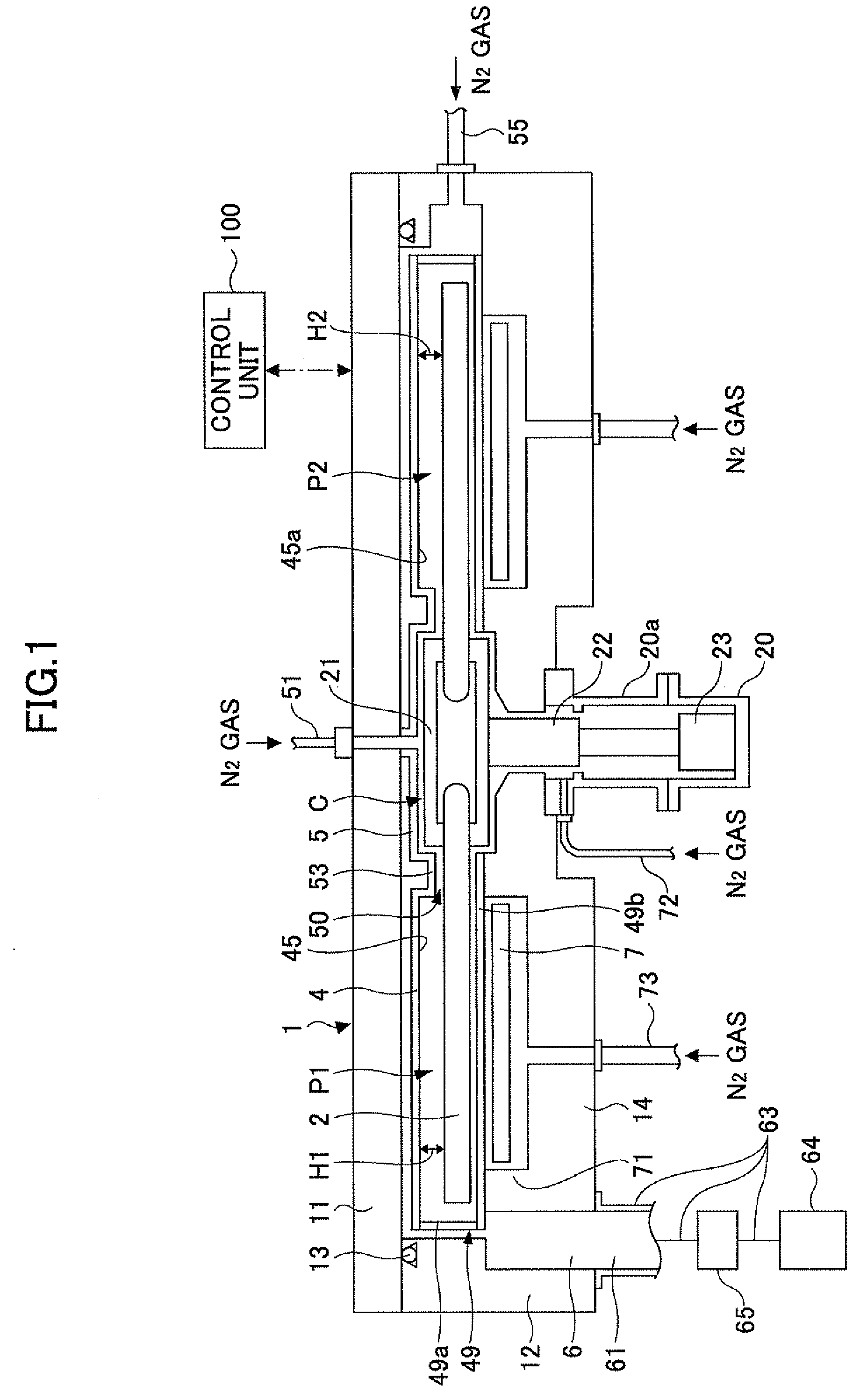
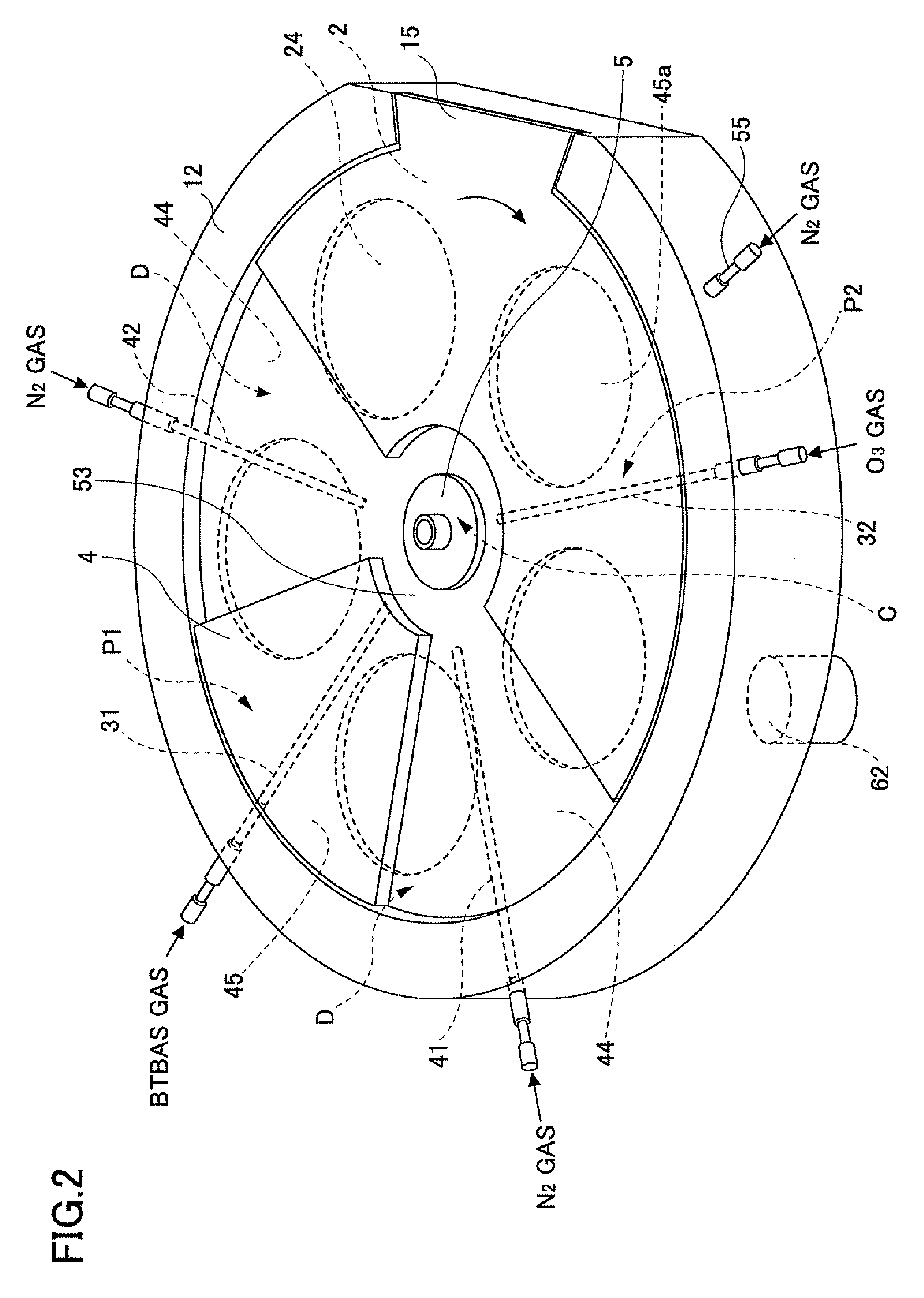
[0053]FIG. 1 is a view in vertical cross section schematically illustrating a structure of the film deposition apparatus in this embodiment of the present invention. FIG. 1 illustrates the vertical cross section along a line B-B in FIG. 3. FIG. 2 is a perspective view schematically illustrating the structure of the film deposition apparatus in this embodiment of the present invention. FIG. 3 is a plan view schematically illustrating the structure of the film deposition apparatus in this embodiment of the present invention. FIGS. 2 and 3 respectively are perspective and plan views in a state where a top plate (or ceiling plate) of a vacuum chamber is removed. FIGS. 4A and 4B are cross sectional views, illustrating first through third spaces, for explaining the film deposition apparatus in this embodiment of th...

first modification

of First Embodiment

[0139]Next, a description will be given of a film deposition apparatus in a first embodiment of the first embodiment of the present invention, by referring to FIG. 13.

[0140]FIG. 13 is a diagram for explaining the film deposition apparatus in this modification, and illustrates a vertical cross section of another example of the shape of the protection top plate in the third lower surface portion. In the following description, parts that are described before are designated by the same reference numerals, and a description thereof may be omitted (the same applies to the modifications and embodiments described hereinafter).

[0141]The film deposition apparatus in this modification differs from the film deposition apparatus of the first embodiment in that a flow passage 47 of the first separation gas is formed to extend in a radial direction of the turntable 2 inside the protection top plate 4 in the third space D.

[0142]Unlike the first embodiment in which a groove is for...

second modification

of First Embodiment

[0145]A description will be given of a film deposition apparatus in a second modification of the first embodiment of the present invention, by referring to FIGS. 14A through 14C.

[0146]FIGS. 14A through 14C are diagrams for explaining the film deposition apparatus in this modification, and illustrate vertical cross sections of other examples of the shape of the lower surface the protection top plate in the third lower surface portion.

[0147]The film deposition apparatus in this modification differs from the film deposition apparatus of the first embodiment in that the third lower surface portion 44 in the third space D is a curved surface.

[0148]As illustrated in FIG. 14A through 14C, unlike the first embodiment in which the third lower surface portion 44 on both sides of the first separation gas supply part 41 is a flat surface, in this modification, the third lower surface portion 44 on both sides of the first separation gas supply part 41 is a curved surface.

[0149...


PUM

PropertyMeasurementUnit
distanceaaaaaaaaaa
diameteraaaaaaaaaa
inner diameteraaaaaaaaaa

Abstract

A film deposition apparatus to form a thin film by supplying first and second reaction gases within a vacuum chamber includes a turntable, a protection top plate, first and second reaction gas supply parts extending from a circumferential edge towards a rotation center of the turntable, and a separation gas supply part provided therebetween. First and second spaces respectively include the first and second reaction gas supply parts and have heights H1 and H2. A third space includes the separation gas supply part and has a height H3 lower than H1 and H2. The film deposition apparatus further includes a vacuum chamber protection part which surrounds the turntable and the first, second and third spaces together with the protection top plate to protect the vacuum chamber from corrosion.

Description

CROSS-REFERENCE TO RELATED APPLICATIONS[0001]This application is based upon and claims the benefit of priority of the prior Japanese Patent Application No. 2008-227024 filed on Sep. 4, 2008, the entire contents of which are incorporated herein by reference.BACKGROUND OF THE INVENTION[0002]1. Field of the Invention[0003]The present invention generally relates to film deposition apparatuses, substrate processing apparatuses, film deposition methods and storage media, and more particularly to a film deposition apparatus, a substrate processing apparatus and a film deposition method for forming a thin film by alternately supplying at least two kinds of source gases, and to a computer-readable storage medium which stores a program which, when executed by a computer, causes the computer to execute such a film deposition method.[0004]2. Description of the Related Art[0005]As a film deposition method of a semiconductor fabrication (or manufacturing) process, there is a known process which c...

Claims


Application Information

Patent Timeline
Patent Type & Authority Patents(United States)
IPC IPC(8): C23C16/455C23C16/44
CPCC23C16/45551C23C16/4401C23C16/45519C23C16/45578H01L21/02H01L21/20
Inventor HONMA, MANABU
Owner TOKYO ELECTRON LTD
Why Eureka
Try Eureka