Electron emitter including carbon nanotubes and its application in gas discharge devices

a carbon nanotube and emitter technology, applied in the manufacture of electric discharge tubes/lamps, electrode systems, discharge tubes luminescnet screens, etc., can solve the problems of reducing the overall energy efficiency of gas discharge devices, boiled off materials can have deleterious effects on the performance of other chemically sensitive materials, and the cathode life is limited, so as to reduce the amount of energy expended, reduce background gas pressure, and increase luminous output

Inactive Publication Date: 2005-09-27
GENERAL ELECTRIC CO
View PDF19 Cites 23 Cited by
  • Summary
  • Abstract
  • Description
  • Claims
  • Application Information

AI Technical Summary

Benefits of technology

[0008]In general, the present invention provides a composition for electron emitters or cathodes of gas discharge devices that can overcome many disadvantages of cathodes of prior-art devices. In the present disclosure, “electron emitters” and “cathodes” are used interchangeably to mean devices, apparatuses, or structures that are capable of providing a stream or a burst of free electrons. The composition of the present invention comprises a mixture of carbon nanotubes and oxygen-containing compounds of alkaline-earth metals. Typically, these oxygen-containing compounds of alkaline-earth metals are alkaline-earth triple oxide. Such an alkaline-earth triple oxide has been used as a coating on the cathode coils of fluorescent lamps to produce a stream of electrons in a thermionic process. The mixture of carbon nanotubes and alkaline-earth triple oxide may be coated on a filament of a metal or a metallic compound having a low work function to form a cathode of a gas discharge device. The composition of the present invention offers a comparable electron current at a lower cathode temperature; thus, helps to reduce the amount of energy expended in maintaining the cathode temperature. Furthermore, the resistance of carbon materials to sputtering in a high vacuum environment offers a reduction in the background gas pressure in gas discharge devices and an accompanying increase in luminous output.

Problems solved by technology

First, this heating requires power, which reduces the overall energy efficiency of the gas discharge device.
Second, the emissive material on the cathode slowly boils off into the surrounding environment at the required elevated temperature, resulting in limited lifetime of the cathode.
This boiled-off material also can have deleterious effects on the performance of other chemically sensitive materials in the gas discharge device, such as phosphors.
Electron emission from the cathode is primarily due to ion impact, which transfers a significant amount of energy to the cathode substrate as a result of the surface collision, resulting in a net energy loss from the device beyond the energy required to liberate the counter-propagating electrons.
These factors result in a low efficiency in generating electrons.
Furthermore, ion impact also results in sputtering of the cathode material and leads to some of the problems of thermionic emission.
However, this required high electric field is not available in typical gas discharge devices such as fluorescent lamps.
However, there has not been any attempt to use carbon nanotubes in the area of gas discharge devices to improve the energy efficiency thereof.

Method used


Image

  • Electron emitter including carbon nanotubes and its application in gas discharge devices
  • Electron emitter including carbon nanotubes and its application in gas discharge devices
  • Electron emitter including carbon nanotubes and its application in gas discharge devices

Examples


example

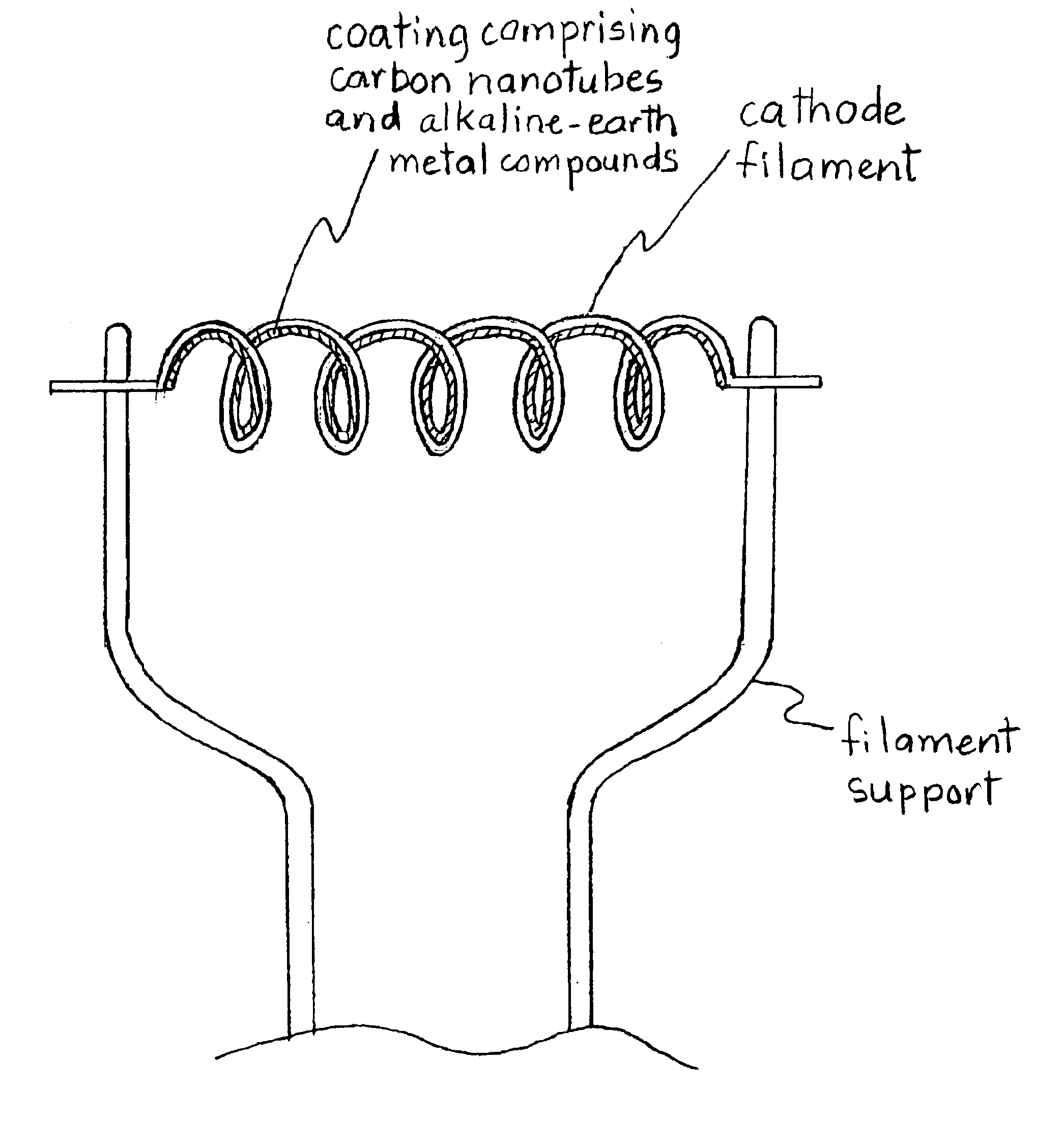
[0018]A mixture of the present invention was made with 25% (by volume) of carbon nanotubes and 75% (by volume) of a conventional alkaline-earth triple carbonate. A small amount of a temporary binder, such as a resin or a starch, may be advantageously added into the mixture. The exact quantity of the temporary binder is not critical. The mixture was deposited by spraying on a coiled cathode of a conventional T8 fluorescent lamp (General Electric Company, Cleveland, Ohio) and the alkaline-earth carbonates were converted to alkaline-earth oxides in a non-oxidizing atmosphere as is well known in the art. The coiled cathodes having the coating layer of carbon nanotubes and alkaline-earth metal oxides were installed in conventional T8 fluorescent lamps. Twenty-four such lamps were produced for testing. In addition, twenty-three T8 fluorescent lamps also were made using the conventional alkaline-earth metal oxide emission mixture without carbon nanotubes for comparative testing. Cathode fa...


PUM

PropertyMeasurementUnit
diameteraaaaaaaaaa
diameteraaaaaaaaaa
temperaturesaaaaaaaaaa

Abstract

An electron emitter includes a coating layer of a mixture of carbon nanotubes and alkaline-earth metal oxides on an electrically conducting structure. The preferred carbon nanotubes are those having a diameter less than about 200 nm. A substantial portion of electron emission is liberated from the carbon nanotubes, thus lessening the requirement on the alkaline-earth oxides. Such an electron emitter is advantageously used in gas discharge devices to increase the energy efficiency thereof.

Description

BACKGROUND OF INVENTION[0001]1. Field of the Invention[0002]The present invention relates to electron emitters that include carbon nanotubes and the application thereof in gas discharge devices. More particularly, the present invention relates to cathodes of fluorescent lamps that include carbon nanotubes.[0003]2. Description of the Related Art[0004]A source of electrons is required in the operation of many devices such as vacuum microelectronic, cathodoluminescent, and gas discharge devices. One common gas discharge device is a fluorescent lamp. In a gas discharge device, the electrons emitted from a cathode migrate to an anode while ionizing a background gas and propagating the discharge. At the cathode of a gas discharge device, the electrons are conventionally generated by thermionic or secondary emission processes. The thermionic emission process employs a low work function material which is raised to a high temperature to liberate electrons into the surrounding environment. Se...

Claims


Application Information

Patent Timeline
Patent Type & Authority Patents(United States)
IPC IPC(8): H01J1/304H01J1/30H01J9/02H01J61/067H01J61/073
CPCB82Y10/00H01J1/304H01J9/025H01J61/0677H01J61/0737H01J2201/30469Y10S977/939
Inventor SUN, XIAO-DONGJIN, FENGSETLUR, ANANT ACHYUT
Owner GENERAL ELECTRIC CO
Why Eureka
Try Eureka