Differential capacitance measurement

a capacitance measurement and differential technology, applied in the field of electrical circuits, can solve the problems of imposing further drawbacks, limiting the desirability of price performance issues, and complicated electronic evaluation circuits that need to be cleverly devised, and achieve the effect of effectiv

Inactive Publication Date: 2005-09-27
DIALOG SEMICONDUCTOR GMBH
View PDF17 Cites 102 Cited by
  • Summary
  • Abstract
  • Description
  • Claims
  • Application Information

AI Technical Summary

Benefits of technology

[0012]A principal object of the present invention is to provide an effective method implementable with the help of very manufacturable integrated circuits for an evaluation circuit for very sensitive capacitive transducers.
[0013]A main object of the present invention is thereby to establish an especially adapted method for a precise, sensitive and yet stable evalution of small capacitive changes or variations.

Problems solved by technology

The needed electronic evaluation circuits however turn out to be rather complicated and have to be cleverly devised.
While such high reliability and high stability devices—also used in the implementation of this invention—offer promise in certain sophisticated applications, price performance issues continue to limit their desirability.
Further, many prior art devices use elaborate analog signal processing for a substantial portion of the circuitry, which imposes further drawbacks.
It is therefore a challenge for the designer of such methods and circuits to achieve a high-quality and low-cost solution.
The apparatus is susceptible of digital implementation and single chip implementation.

Method used


Image

  • Differential capacitance measurement
  • Differential capacitance measurement
  • Differential capacitance measurement

Examples


Embodiment Construction

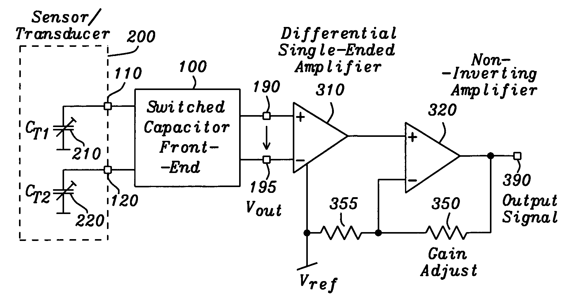
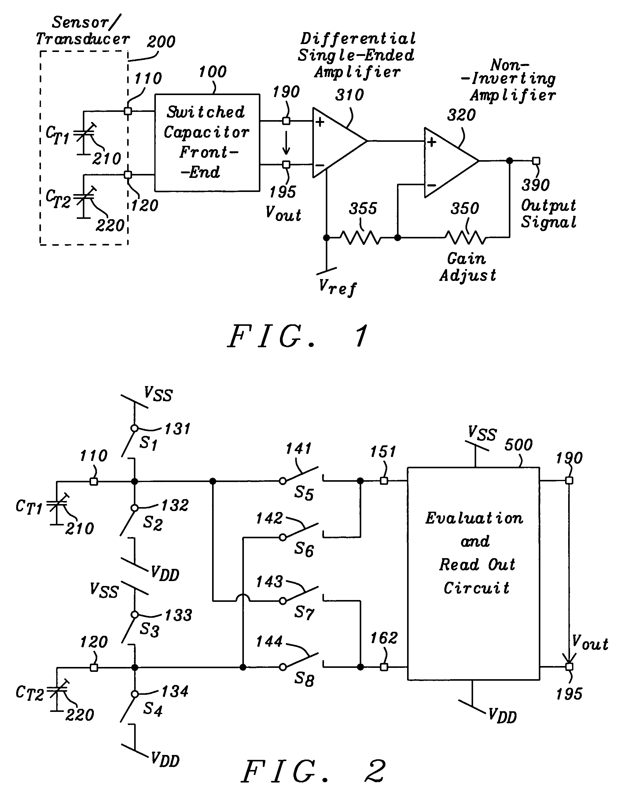
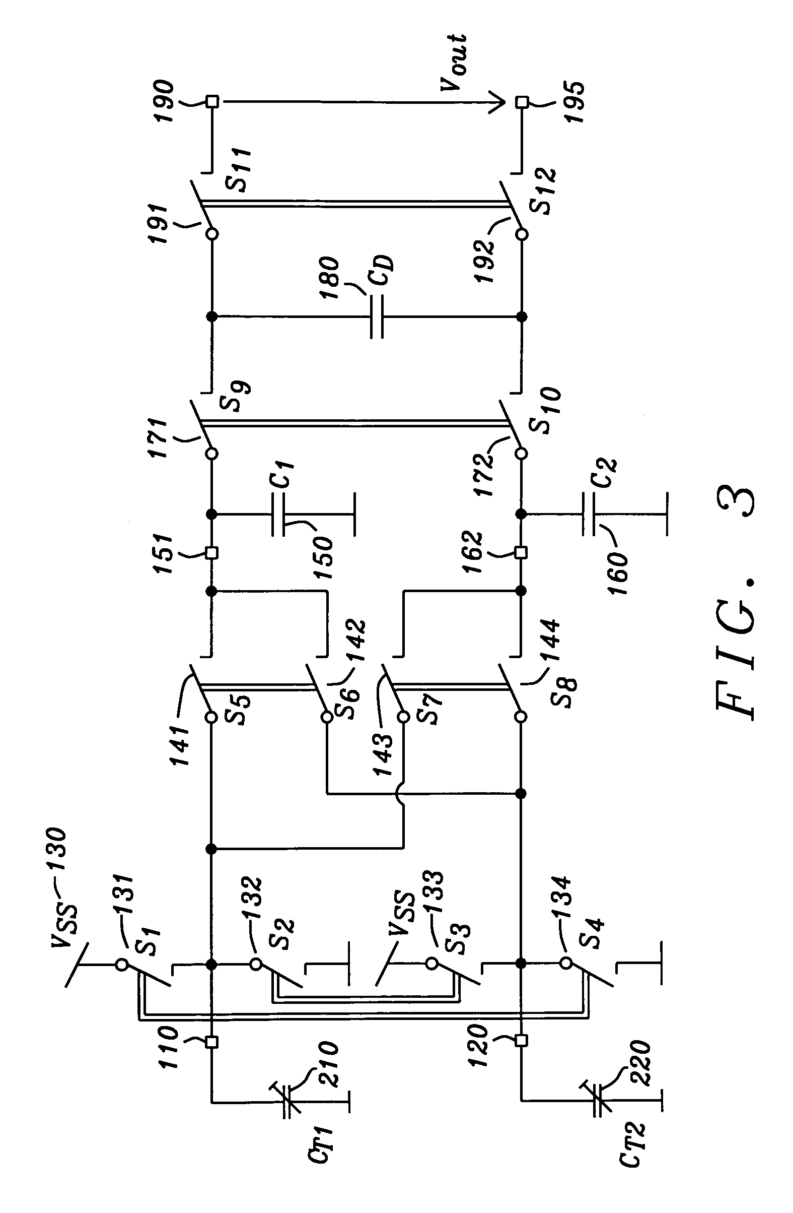
[0041]The preferred embodiments disclose a novel circuit arrangement and a new method for differential capacitance measurements, capable of a very sensitive evaluation of small capacitance varaiations within a differential capacitor arrangement. These variations are evaluated in devices for touch or actuator buttons e.g. for implementing non-mechanical switches as used for example in elevator control panels or vandal-proof telephone dialers, said principle is further used for building high reliability switches for keyboards with capacitive contacts in computer systems or any other industrial equipment e.g. for tooling machinery, but also in control devices for commercial and consumer products e.g. television sets or video recorders. Capacitance variations are analyzed also within proximity sensors using the change of the dielectric constant of a dedicated capacitor element. Sensors for detecting humidity or even measuring moisture also use the evaluation of small changes within a di...


PUM

PropertyMeasurementUnit
response timeaaaaaaaaaa
capacitanceaaaaaaaaaa
electrical energyaaaaaaaaaa

Abstract

A circuit and method are given, which realizes a stable yet sensitive differential capacitance measuring device with good RF-suppression and with very acceptable noise features for use in capacitive sensor evaluation systems. By evaluating the difference of capacitor values only—with the help of a switched capacitor front-end—large spreads of transducer capacitor values are tolerable. Furthermore a mode of operation can be set up, where no essential galvanic connection between sensor input and the active read-out input at any given time is existing. The solution found exhibits a highly symmetrical construction. Using the intrinsic advantages of that solution the circuit of the invention is manufactured as an integrated circuit with standard CMOS technology at low cost.

Description

BACKGROUND OF THE INVENTION[0001](1) Field of the Invention[0002]The invention relates generally to electronic circuits for the evaluation of the physical effects on capacitive components and more particularly, to circuits for detecting capacitance variations at capacitive sensors or transducers and even more particularly to a circuit for the detection of the x-, y- and z-coordinate position changes measured with displacement-responsive devices such as joysticks built with variable capacitors. Both, a circuit and a method are disclosed.[0003](2) Description of the Prior Art[0004]Many electronic sensoring devices on the market today are built by eploiting capacitive effects by some means or other. Amongst them there are devices for touch or actuator buttons e.g. implementing a non-mechanical switch as used for example in elevator control panels or vandal-proof telephone dialers. Further on high reliability switches for keyboards are manufactured with such capacitive contacts normally...

Claims


Application Information

Patent Timeline
Patent Type & Authority Patents(United States)
IPC IPC(8): G01L9/12G01D5/24G01D5/12G01R27/26G01D5/241
CPCG01D5/241G01R27/2605
Inventor KNOEDGEN, HORST
Owner DIALOG SEMICONDUCTOR GMBH
Why Eureka
Try Eureka