Supercharge Your Innovation With Domain-Expert AI Agents!

Logic circuit module having power consumption control interface and a recording medium storing the module

Inactive Publication Date: 2005-09-27
RENESAS ELECTRONICS CORP
View PDF17 Cites 59 Cited by
  • Summary
  • Abstract
  • Description
  • Claims
  • Application Information

AI Technical Summary

Benefits of technology

[0009]It is another object of the invention to provide a method of facilitating a system LSI designer to input specifications for the power consumption control of a system LSI when the system LSI is configured.

Problems solved by technology

The above-described conventional methods do not provide, however, sufficient consideration of a system LSI constituted of a combination of a plurality of reusable logic circuit modules (IP cores: IP is an acronym for Intellectual Property).
Although the above-described conventional methods describe the technique of a power voltage control to control a power consumption, they do not disclose a method of changing the power voltage of only some circuit modules of a system LSI.

Method used


Image

  • Logic circuit module having power consumption control interface and a recording medium storing the module
  • Logic circuit module having power consumption control interface and a recording medium storing the module
  • Logic circuit module having power consumption control interface and a recording medium storing the module

Examples


first embodiment

[0043]the invention will be described with reference to the accompanying drawings.

[0044]The process of designing a system LSI by using IP cores embodying the invention will be described first, and then the whole structure of a specific system using a system LSI embodying the invention will be described. An example of the system operation will be described thereafter.

[0045]FIG. 22 briefly shows the relation between a system LSI according to an embodiment and IP cores constituting the system LSI.

[0046]In FIG. 22, reference numeral 2201 represents a system LSI, and reference numerals 2202 to 2205 represent cores disposed in the system LSI.

[0047]A system LSI designer selects necessary cores in accordance with the specification of a system LSI to be designed and receives (buys) the cores from core providers 1 to 4. Generally, the system LSI designer is provided with an IP core by receiving a recording medium storing design information or by receiving the same information as that stored i...

second embodiment

[0151]Next, the invention will be described with reference to FIGS. 10 to 13 and FIGS. 23 and 24.

[0152]FIG. 23 shows how a system embodying the invention is used.

[0153]Reference numeral 2300 represents a system-in-package (SIP) chip, 2301 represents a system chip in the package, 2302 represents a radio frequency (RF) module, 2303 represents a portable terminal, reference numeral 2304 represents a base station for portable terminals, 2307 and 2308 represent consumption power control interfaces, 2305 represents a signal line for consumption power control, 2306 represents a signal line for RF module control, 2309 represents a battery, 2308 represents a signal line for battery control, and 2310 represents a central server.

[0154]SIP 2300 is constituted of the system chip 2301 and RF module 2302. SIP 2300 is built in the system portable terminal 2303.

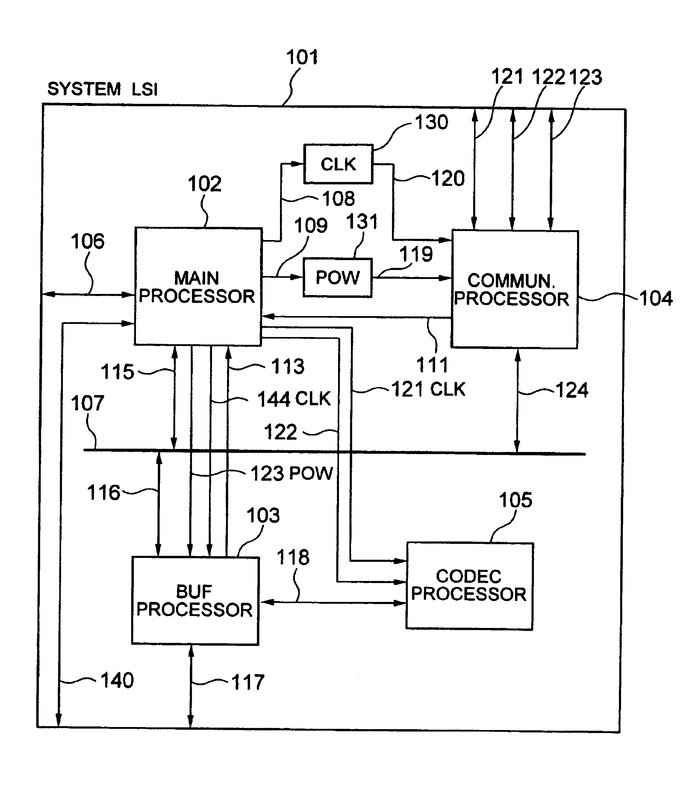
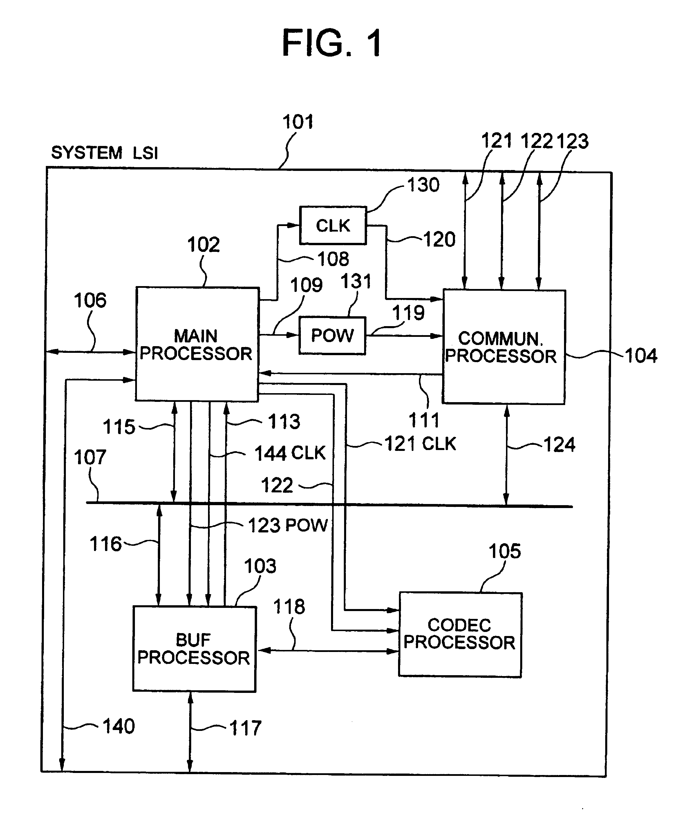
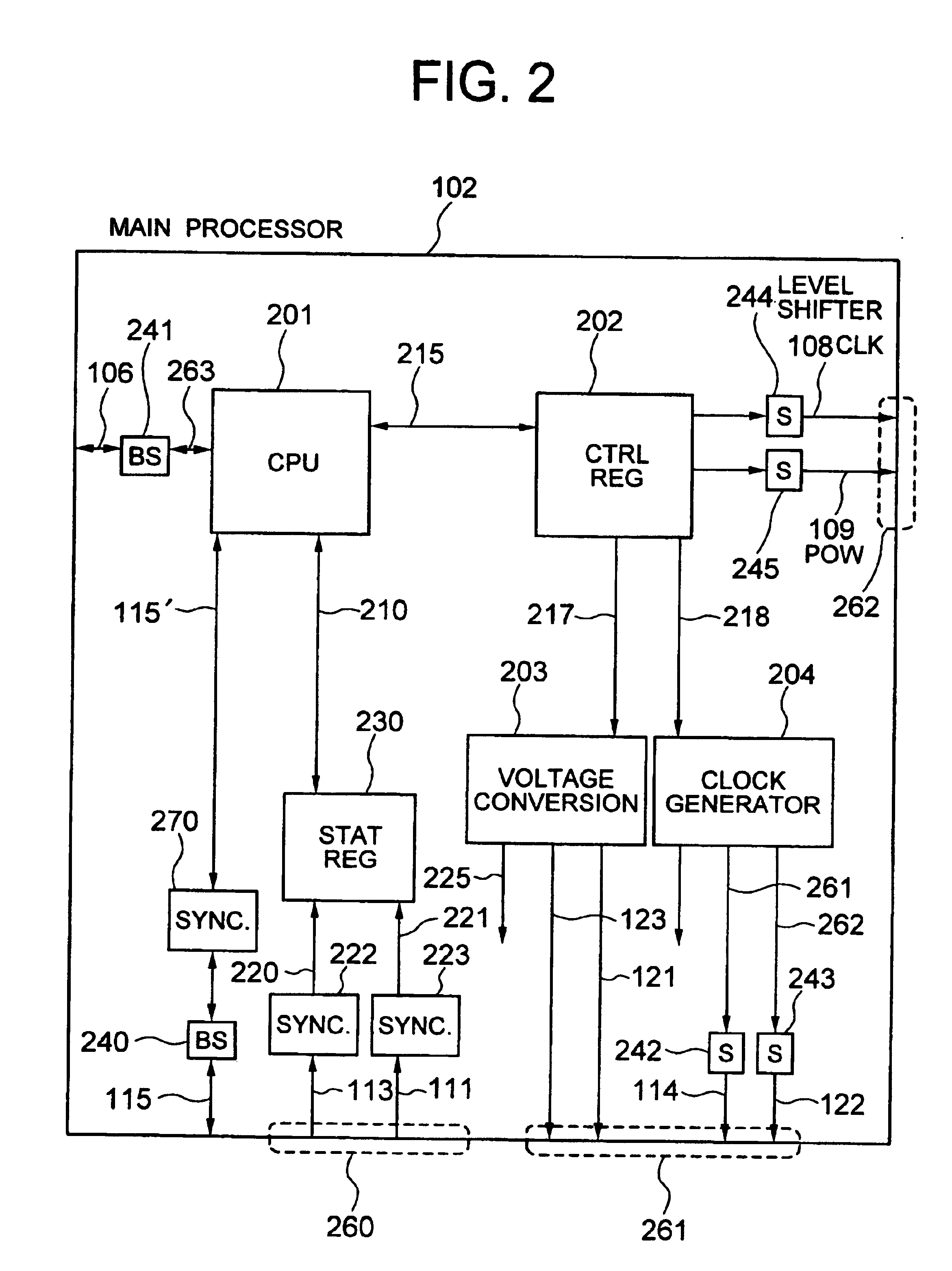
[0155]The system chip 2301 includes a main processor, a battery monitor processor, a buffer processor, and a CODEC processor.

[0156]The RF mo...


PUM


Abstract

Consumption power control is provided for a system LSI made of a combination of a plurality of reusable logic circuit modules, i.e., Intellectual Property (IP) cores. Hardware resources such as interfaces and registers for the consumption power control of other IP cores are prepared and controlled by software for the consumption power control of a system LSI. The consumption power can be controlled at an IP core level. A method is provided which facilitates a system LSI designer to enter a consumption power control specification of a system LSI when the system LSI is configured.

Description

[0001]The present application is a continuation of application Ser. No. 09 / 963,494, filed Sep. 27, 2001 now U.S. Pat. No. 6,717,434, the contents of which are incorporated herein by reference.BACKGROUND OF THE INVENTION[0002]The present invention relates to a logic circuit module and a semiconductor integrated circuit having a recording medium storing the module, and more particularly to a semiconductor integrated circuit having a function of controlling a power consumption of another semiconductor integrated circuit.[0003]An example of a conventional method of lowering a power consumption of a semiconductor integrated circuit is described in JP-A-07-20968. With this method, the consumption power of a computer is reduced by dynamically changing the operating voltage and frequency. Namely, by dynamically lowering the operating voltage and clock speed, the power consumption of the computer system is reduced.[0004]An example of an interface to the external is described in JP-A-06-20275...

Claims


Application Information

Patent Timeline
IPC IPC(8): G06F1/32G06F17/50
CPCG06F1/32G06F17/5045G06F30/30
Inventor TAKAHASHI, YOSHITAKASAITO, MASAHIKONAYA, HIDEMITSUKIKUCHI, MUTSUMIHOTTA, TAKASHI
Owner RENESAS ELECTRONICS CORP
Features
  • R&D
  • Intellectual Property
  • Life Sciences
  • Materials
  • Tech Scout
  • Unparalleled Data Quality
  • Higher Quality Content
  • 60% Fewer Hallucinations
Learn More