Gray code counter

a code counter and code technology, applied in the field of gray code counters, can solve problems such as electrical noise, signal interference, system malfunction, etc., and achieve the effect of reducing electric nois

Inactive Publication Date: 2005-09-27
SHARP KK
View PDF8 Cites 12 Cited by
  • Summary
  • Abstract
  • Description
  • Claims
  • Application Information

AI Technical Summary

Benefits of technology

[0029]An object of the present invention is to provide a Gray code counter that permits interlaced counting and that achieves interlaced counting without causing change in more than two bits simultaneously. Another object of

Problems solved by technology

The greater the number of bits in which such change takes place simultaneously, the more power current flows through the system in which the counter is provided, causing electric noise.
This may lead to interference between signals within the system, and thus to malfunctioning of the system.
Moreover, in a solid-state image sensor, it is sometimes necessary to take both still and moving p

Method used


Image

  • Gray code counter
  • Gray code counter
  • Gray code counter

Examples


first embodiment

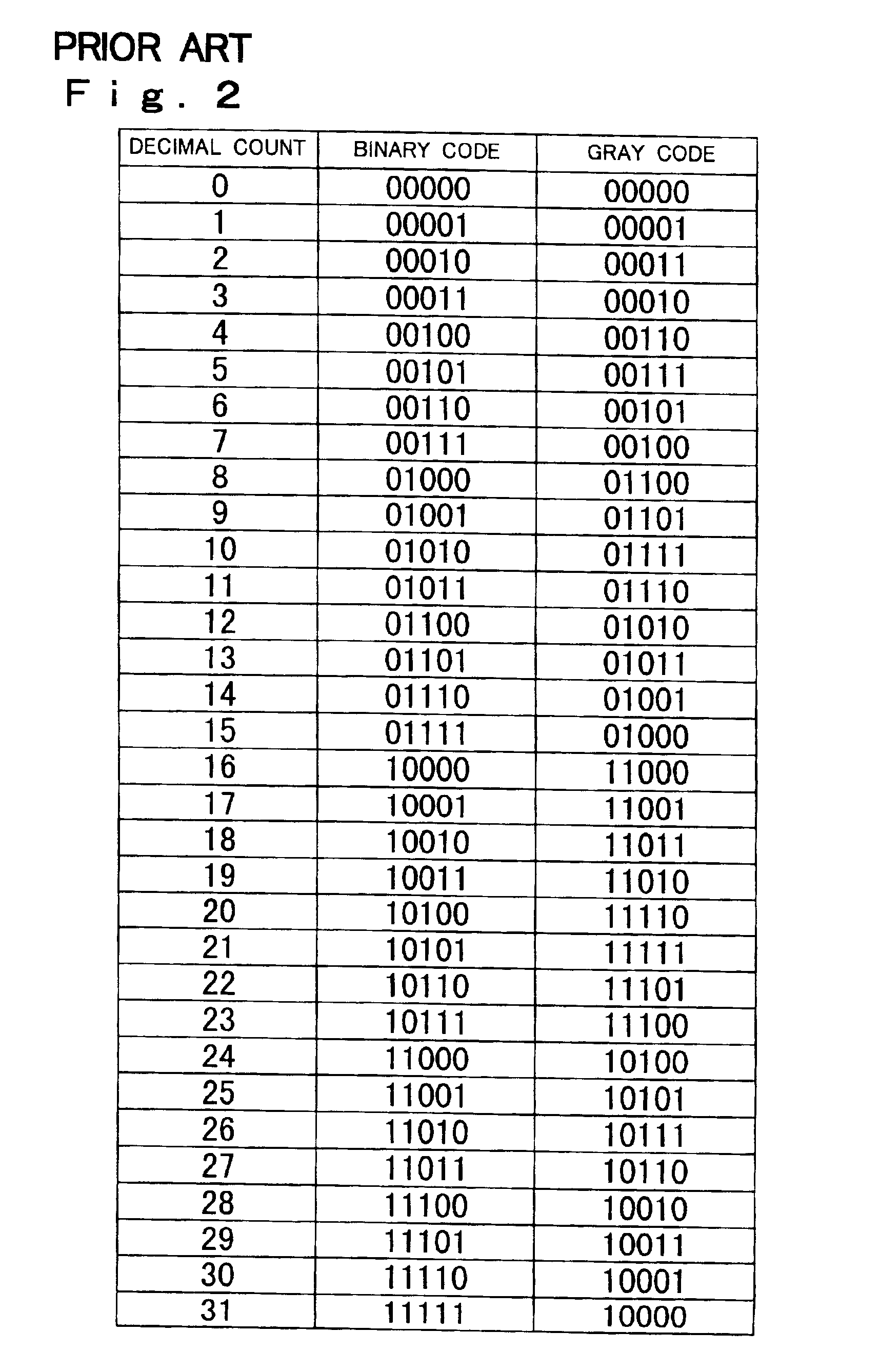
[0063]When counting is performed with 2M−1 counts skipped at a time and M=1, i.e. when counting is performed with one count skipped at a time, the Gray code counter 1 of the first embodiment counts in this way: 0, 2, 4, 6, . . . . FIG. 3 is a diagram showing decimal counts and the corresponding Gray code in a case where counting is performed with one count skipped at a time. As will be clear from the FIG. 3, in the Gray code obtained by counting with one count skipped at a time, the zeroth bit (the lowest bit) is inverted every time the count changes, and the way the (α+1)th bit belonging to the highest four bits (the fourth to first bits) changes every time the count changes is the same as the way the αth bit belonging to the lowest four bits (the third to zeroth bits) changes as the Gray code counter 2 counts from 0 to 15 (see FIG. 2). Here, where M=1, α is a whole number in the range from 0 to 3.

[0064]When counting is performed with 2M−1 counts skipped at a time and M=2, i.e. whe...

second embodiment

[0078]Next, examples of the configuration of the individual circuit blocks of the Gray code counter of the second embodiment shown in FIG. 8 will be described. First, the output value converter 3′ and the initial setting circuit 7 will be described.

[0079]Now, the relationship, as observed in a case where counting is started at a specified value, between the Gray code output data obtained by consecutive counting and the Gray code output data obtained by counting with 2M−1 counts skipped at a time will be considered.

[0080]When counting is performed with 2M−1 counts skipped at a time and M=1, i.e. when counting is performed with one count skipped at a time, such counting is possible by starting at either “0” or “1,” which are to be dealt with as different cases. FIG. 17A is a diagram showing decimal counts and the corresponding Gray code in a case where counting is started at “0,” and FIG. 17B is a diagram showing decimal counts and the corresponding Gray code in a case where counting ...


PUM


Abstract

Conventionally, it is difficult to design the logic of a Gray code counter that can be used in interlaced counting. Even though interlaced counting is possible with a Gray code counter, the number of simultaneously changing bits increases greatly depending on the number of counts skipped at a time. To overcome these problems, a Gray code counter according to the present invention has a consecutively counting Gray code counter that counts in increments or decrements of one, and an output value converter circuit that converts the Gray code data output from the consecutively counting Gray code counter into a Gray code corresponding to decimal counts as obtained by counting with (2 raised to a particular power minus 1) counts skipped at a time.

Description

BACKGROUND OF THE INVENTION[0001]1. Field of the Invention[0002]The present invention relates to a Gray code counter.[0003]2. Description of the Prior Art[0004]Some solid-state image sensors adopt a scanning circuit of a decoder type. A decoder-type scanning circuit is provided with a counter, and scans the address that coincides with the value output from the counter. By making this counter perform the desired counting operation, it is possible to achieve image sensing.[0005]Conventionally, such a decoder-type scanning circuit employs a binary counter. However, in a binary counter, an increment or decrement by one of its decimal count sometimes causes simultaneous change in a plurality of bits. For example, in a 5-bit binary counter, when its decimal count changes from “0” to “1,” as FIG. 2 shows, the binary code changes from (00000) to (00001), causing change only in one bit. By contrast, when the decimal count changes from “15” to “16,” as FIG. 2 shows, the binary code changes fr...

Claims


Application Information

Patent Timeline
IPC IPC(8): H03K23/00H04N5/335H03K21/40H03K23/66H03M7/16
CPCH03K23/005H04N5/335H04N25/00H03K23/00
Inventor HAMAGUCHI, MUTSUMI
Owner SHARP KK
Why Eureka
Try Eureka