
Magnetic head having a heat dissipating structure

a heat dissipation structure and head technology, applied in the field of magnetic heads, can solve the problems of degrading data reading and writing performance, generating a large amount of heat, and reducing the performance of the head, so as to reduce the thermally induced performance degradation

Inactive Publication Date: 2005-09-27
SEAGATE TECH LLC
View PDF22 Cites 29 Cited by
  • Summary
  • Abstract
  • Description
  • Claims
  • Application Information

AI Technical Summary

Benefits of technology

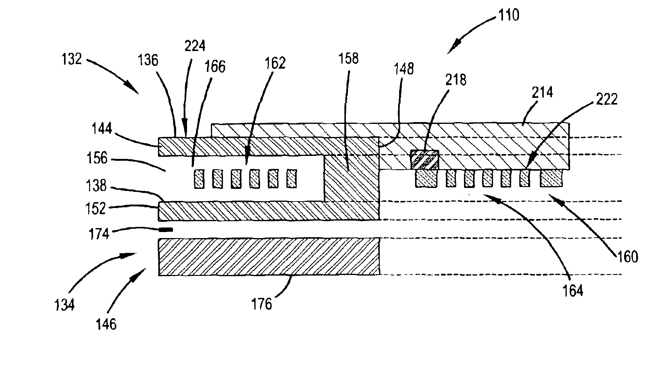
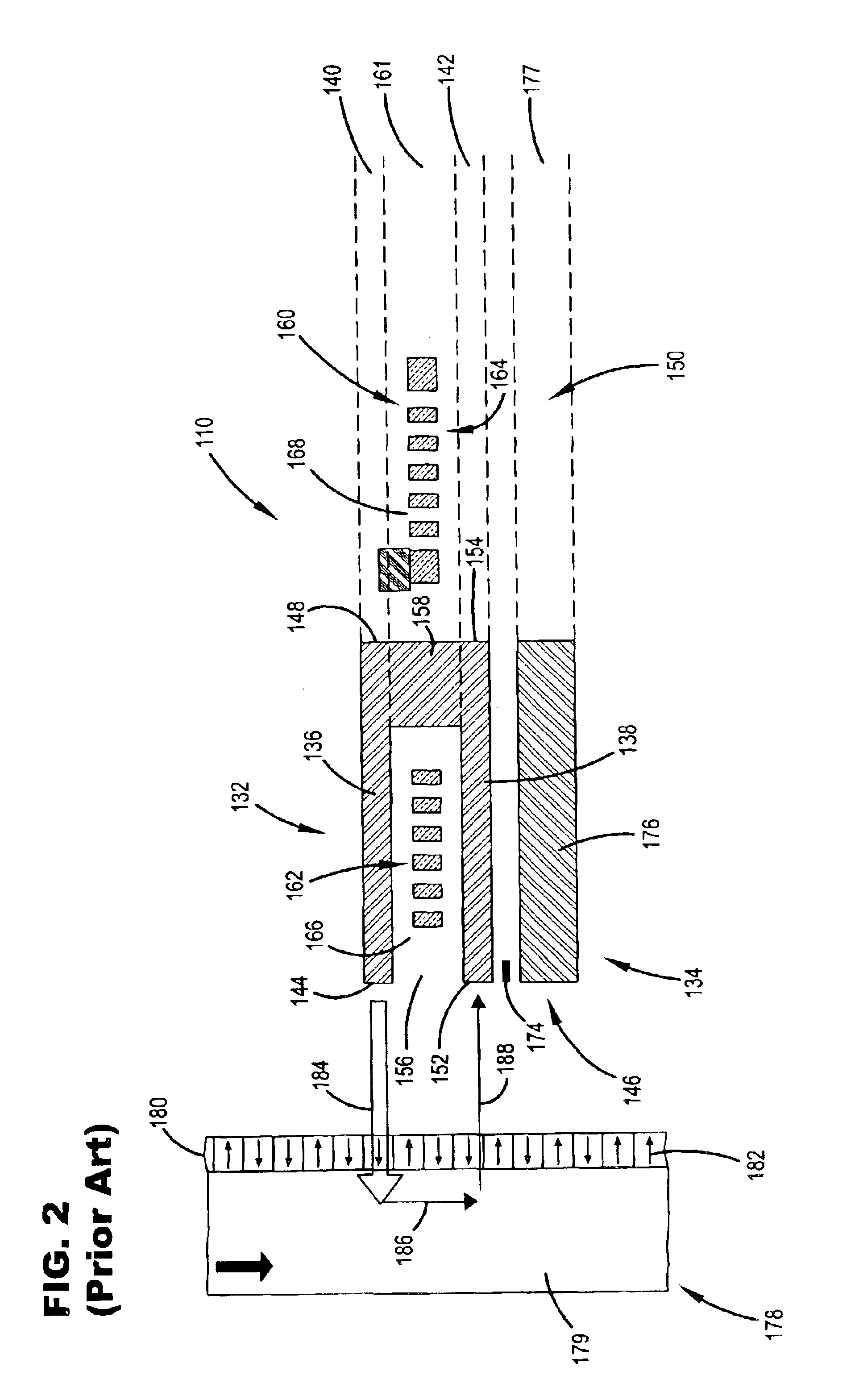
[0008]The present invention is directed to a magnetic head that includes a heat dissipating structure for reducing thermally induced performance degradation. The magnetic head includes top and bottom writer poles, a writer conducting coil, and a heat dissipating structure. The top and bottom writer poles are respectively formed in top and bottom pole layers. Each pole includes a pole tip at an air-bearing surface (ABS) and a back side adjacent a back region. The writer conducting coil is formed in a coil layer, extends from the ABS, includes a first portion disposed between the top and bottom writer poles and a second portion located beyond the top and bottom writer poles. The heat dissipating structure includes a top heat transfer sheet formed of a thermally conductive material and overlaying the second portion of the conducting coil; a bottom heat transfer sheet formed of a thermally conductive material in the back region of the bottom pole layer, displaced from the back side of the bottom writer pole, and underlaying the second portion of the conducting coil; a first side heat transfer member formed of a thermally conductive material in the coil layer adjacent a first side of the conducting coil; and / or a second side heat transfer member formed of a thermally conductive material in the coil layer adjacent a second side of the conducting coil.

Problems solved by technology

As a result, a greater amount of heat is generated within the heads, which can degrade their performance.
This thermally induced expansion of the head can degrade data reading and writing performance by varying the head-media spacing, particularly at the active region of the ABS.

Method used


Image

  • Magnetic head having a heat dissipating structure
  • Magnetic head having a heat dissipating structure
  • Magnetic head having a heat dissipating structure

Examples


Embodiment Construction

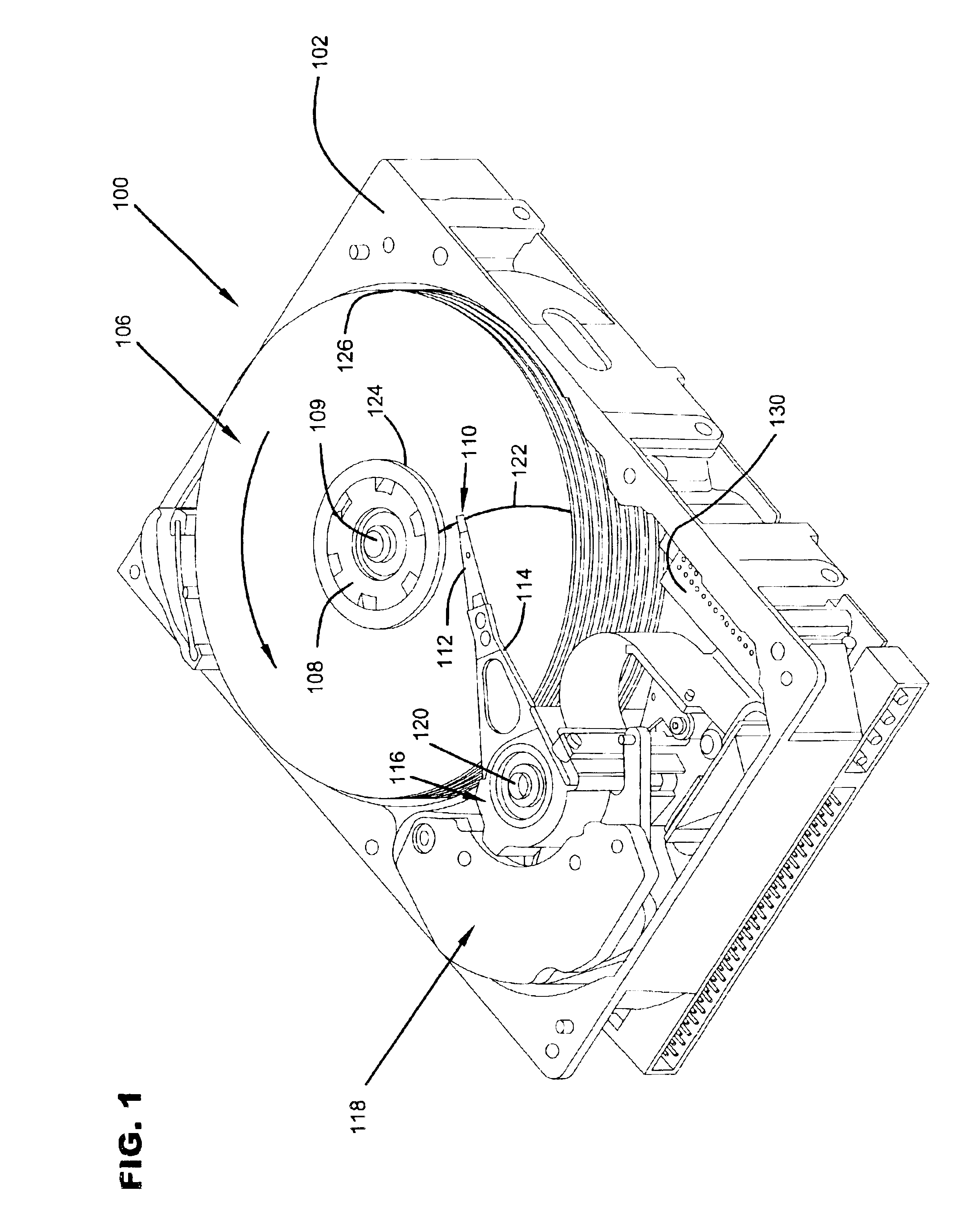
[0018]FIG. 1 is an isometric view of a disc drive 100 in which embodiments of the present invention are useful. Disc drive 100 includes a housing with a base 102 and a top cover (not shown). Disc drive 100 further includes a disc pack 106, which is mounted on a spindle motor (not shown) by a disc clamp 108. Disc pack 106 includes a plurality of individual discs, which are mounted for co-rotation about central axis 109. Each disc surface has an associated read / write head 110 which is mounted to disc drive 100 for communication with the disc surface. In the example shown in FIG. 1, heads 110 are each carried by sliders that are supported by suspensions 112, which are in turn attached to track accessing arms 114 of an actuator 116. The actuator shown in FIG. 1 is of the type known as a rotary moving coil actuator and includes a voice coil motor (VCM), shown generally at 118. Voice coil motor 118 rotates actuator 116 with its attached heads 110 about a pivot shaft 120 to position heads ...


PUM

PropertyMeasurementUnit
thicknessaaaaaaaaaa
thermally conductiveaaaaaaaaaa
heataaaaaaaaaa

Abstract

A magnetic head having a heat dissipating structure formed of a thermally conductive material that includes a top heat transfer sheet overlaying a second portion of a writer conducting coil; a bottom heat transfer sheet formed in a back region of a bottom pole layer, displaced from a back side of a bottom writer pole, and underlaying the second portion of the writer conducting coil; a first side heat transfer member formed in a coil layer adjacent a first side of the writer conducting coil; and / or a second side heat transfer member formed in the coil layer adjacent a second side of the writer conducting coil.

Description

CROSS-REFERENCE TO RELATED APPLICATION[0001]This application claims priority from U.S. Provisional Application No. 60 / 422,085 filed on Oct. 29, 2002 for inventors Christopher J. T. Rea, Ladislav Rudolf Pust, Michael Christopher Kautzky and Mallika Kamarajugadda and entitled WRITE INDUCED PTR SUPPRESSION STRUCTURES.FIELD OF THE INVENTION[0002]The present invention relates generally to magnetic heads for use in disc drive storage systems, and more particularly, but not by limitation to a magnetic head having a heat dissipating structure that reduces the likelihood of thermally induced head performance degradation.BACKGROUND OF THE INVENTION[0003]Disc drives are the primary devices employed for mass storage of computer programs and data. Disc drives typically use rigid discs, which are coated with a magnetizable medium to form a recording layer in which data can be stored in a plurality of circular, concentric data tracks. Disc drives employ read / write heads that includes a reader for ...

Claims


Application Information

Patent Timeline
Patent Type & Authority Patents(United States)
IPC IPC(8): G11B5/31G11B5/33G11B5/39G11B5/40
CPCG11B5/3103G11B5/313G11B5/3133G11B5/3136G11B5/332G11B5/3903G11B5/3967G11B5/40
Inventor REA, CHRISTOPHER JAMES THOMPSONPUST, LADISLAV RUDOLFKAUTZKY, MICHAEL CHRISTOPHERKAMARAJUGADDA, MALLIKA
Owner SEAGATE TECH LLC
Learn More