Spray head and air atomizing assembly

a technology of air atomization and spray head, which is applied in the direction of spray nozzles, liquid spraying apparatus, coatings, etc., can solve the problems of limited performance and less than satisfactory, and achieve the effects of improving atomization, high surface tension materials, and high viscosity

Inactive Publication Date: 2005-10-04
RUBBERMAID INDAL PRODS CORP
View PDF8 Cites 46 Cited by
  • Summary
  • Abstract
  • Description
  • Claims
  • Application Information

AI Technical Summary

Benefits of technology

[0011]In general, the air atomizing assembly in accordance with the present invention may be used with a conventional air sprayer with a nozzle opening as is conventional in the art. Such air sprayer may be provided with an application fluid supply tube or conduit for a single component material r with an elongated mixing tube for a two component material. In the preferred embodiment, the air atomizing assembly of the present invention includes an air atomizing tip which has a generally outer conical surface that converges in the direction of the nozzle opening. This conical surface is provided with a plurality of atomizing air flow paths or grooves which spiral along the conical surface as it converges. The air atomizing tip is used in combination with an atomizing assembly cap which includes an inner conical surface that mates with a portion of the exterior conical surface of the tip to form a plurality of air passages defined by the grooves in the exterior conical surface of the atomizer tip. The cross-sectional configuration of these air passages as they exit from the atomizing assembly has a generally flattened configuration in which the circumferential dimension of the passages are preferably at least about twice the depth or radial dimension of such passages. Because of the generally flat shape of the air passages at the exit end of the assembly, the airflow has a shear effect on the exiting application fluid. This shear effect tends to break up and shear portions of the application fluid from adjacent portions and results in significantly improved atomization of the application fluid. This is particularly true for materials having a high viscosity and / or high surface tension.
[0014]Another object of the present invention is to provide an air atomizing assembly which provides improved atomization for high viscosity and / or high surface tension materials.

Problems solved by technology

While many of the air atomizing assemblies of the prior art are generally acceptable when being used to atomize relatively low viscosity materials such as paint which are designed to be broken up and atomized easily, their performance is limited and less than satisfactory when used to atomize high viscosity materials (in excess of about 3,000 centipoises) and materials which have a high surface tension such as epoxies, urethanes, polyureas and other adhesives.
These high viscosity and high surface tension materials are difficult to atomize and thus tend to “string” a lot as the application material travels from the spray nozzle to the substrate.

Method used


Image

  • Spray head and air atomizing assembly
  • Spray head and air atomizing assembly
  • Spray head and air atomizing assembly

Examples


Embodiment Construction

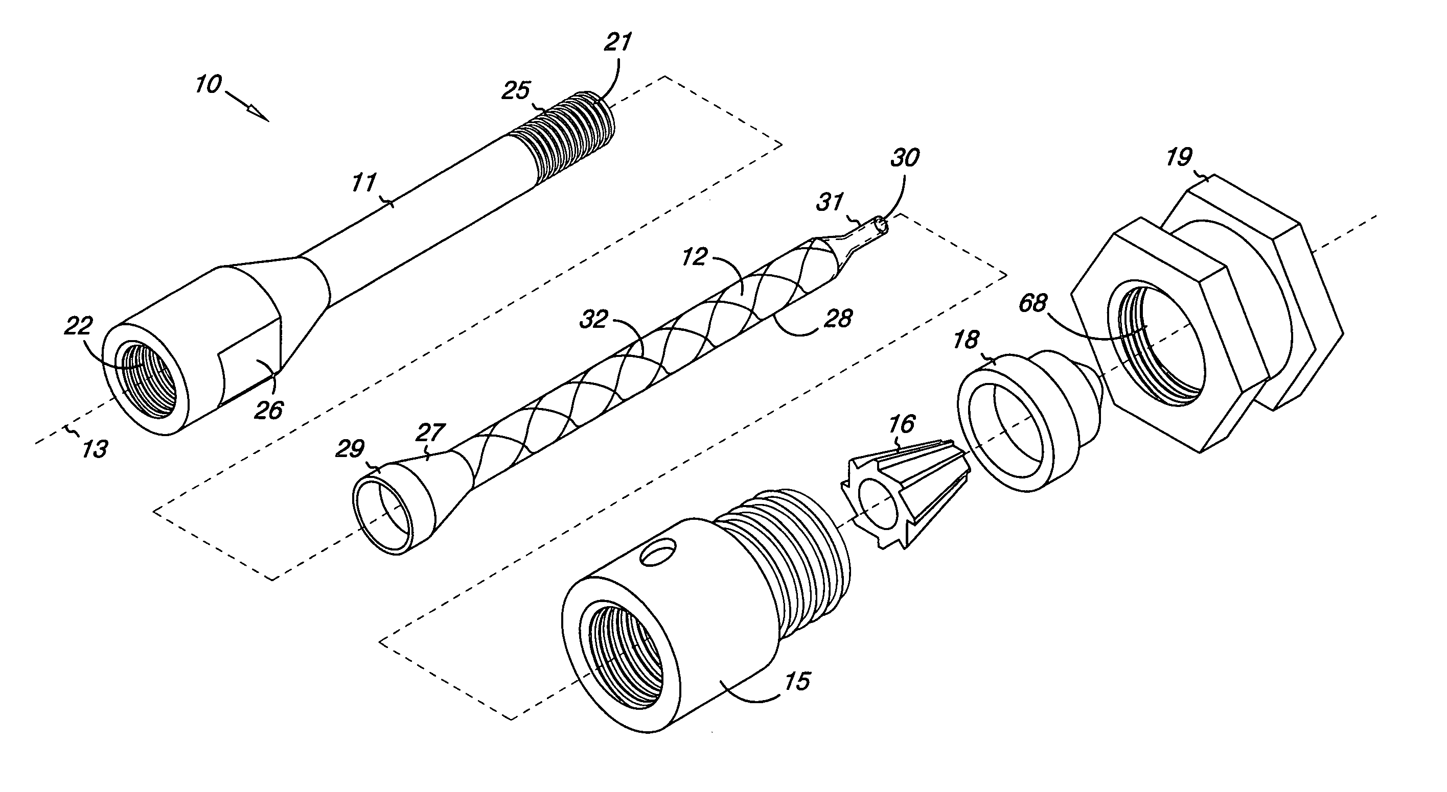
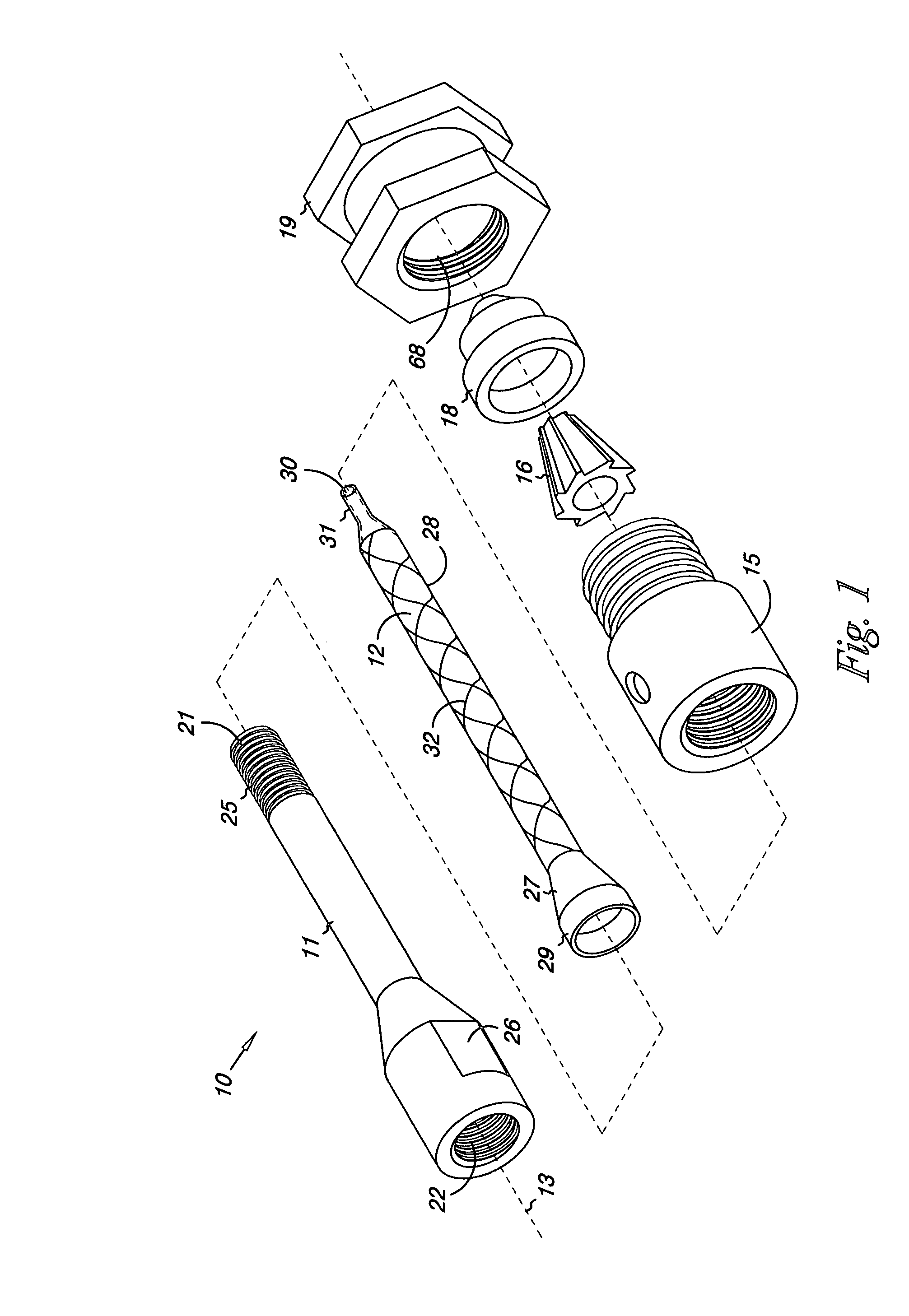
[0032]The present invention relates generally to a spray head and an air atomizing assembly incorporated therein. As will be described in greater detail below, the spray head of the present invention may be used with an application fluid mixing assembly which in turn is designed for use with an application fluid spray or delivery device such as an air atomized paint sprayer or an air atomized spray or application device. Such sprayers or other application devices are used to deliver application fluids such as paints, adhesives, sealants, semi-liquids and the like, to a substrate. In describing the present invention, the preferred embodiment will be described with respect to an air atomized paint or other application fluid sprayer.

[0033]The present invention has applicability to the application of both single component materials as well as two or multiple component materials. Two or multiple component materials are generally chemically cured and thus are commonly applied through a mi...


PUM


Abstract

A spray head and air atomizing assembly for providing atomizing air in an air sprayer or other delivery device in which the atomizing assembly includes converging, spiral atomizing fluid passageways.

Description

BACKGROUND OF THE INVENTION[0001]1. Field of the Invention[0002]The present invention relates generally to a spray head air atomizing assembly and more specifically to an air atomizing assembly to control the flow of atomizing air in a fluid spray or other delivery device such as an air sprayer for spraying paints, adhesives, coatings, and other semi-liquid materials.[0003]2. Description of the Prior Art[0004]Two common types of spray or delivery devices exist for spraying or delivering a fluid to a substrate. One such device is a so-called airless type sprayer or delivery device in which an application fluid is forced through one or more nozzle openings at high pressure. With this type of device, the fluid is atomized or disbursed into tiny droplets as a result of the pressurized fluid passing through the nozzle opening.[0005]A second such device is an air or air atomized spray gun or delivery device in which the application fluid passes through a nozzle orifice, at pressures usual...

Claims


Application Information

Patent Timeline
Patent Type & Authority Patents(United States)
IPC IPC(8): B05B7/10B05B7/02B05B7/06
CPCB05B7/0861B05B7/10B05B7/0408B05B7/066B05C17/005
Inventor ANDERSON, STEVEN R.
Owner RUBBERMAID INDAL PRODS CORP
Why Eureka
Try Eureka