Sleeve valve for controlling fluid flow between a hydrocarbon reservoir and tubing in a well and method for the assembly of a sleeve valve

Inactive Publication Date: 2005-10-04
WELL INNOVATION ENG
View PDF16 Cites 92 Cited by
  • Summary
  • Abstract
  • Description
  • Claims
  • Application Information

AI Technical Summary

Benefits of technology

[0015]The object of the invention is to provide a solution to the aforementioned problem associated with leakage of the sleeve valves when they are subjected

Problems solved by technology

A high differential pressure in itself can cause leakage.
In addition, differential pressure can lead to deformation of the sleeve valves, which can cause the sleeve valves to leak when closed.
In sleeve valves where the sealing is based on gaskets, it has been found that leakage often occurs after some time when the valve is in a closed position, and gaskets ar

Method used


Image

  • Sleeve valve for controlling fluid flow between a hydrocarbon reservoir and tubing in a well and method for the assembly of a sleeve valve
  • Sleeve valve for controlling fluid flow between a hydrocarbon reservoir and tubing in a well and method for the assembly of a sleeve valve
  • Sleeve valve for controlling fluid flow between a hydrocarbon reservoir and tubing in a well and method for the assembly of a sleeve valve

Examples


Embodiment Construction

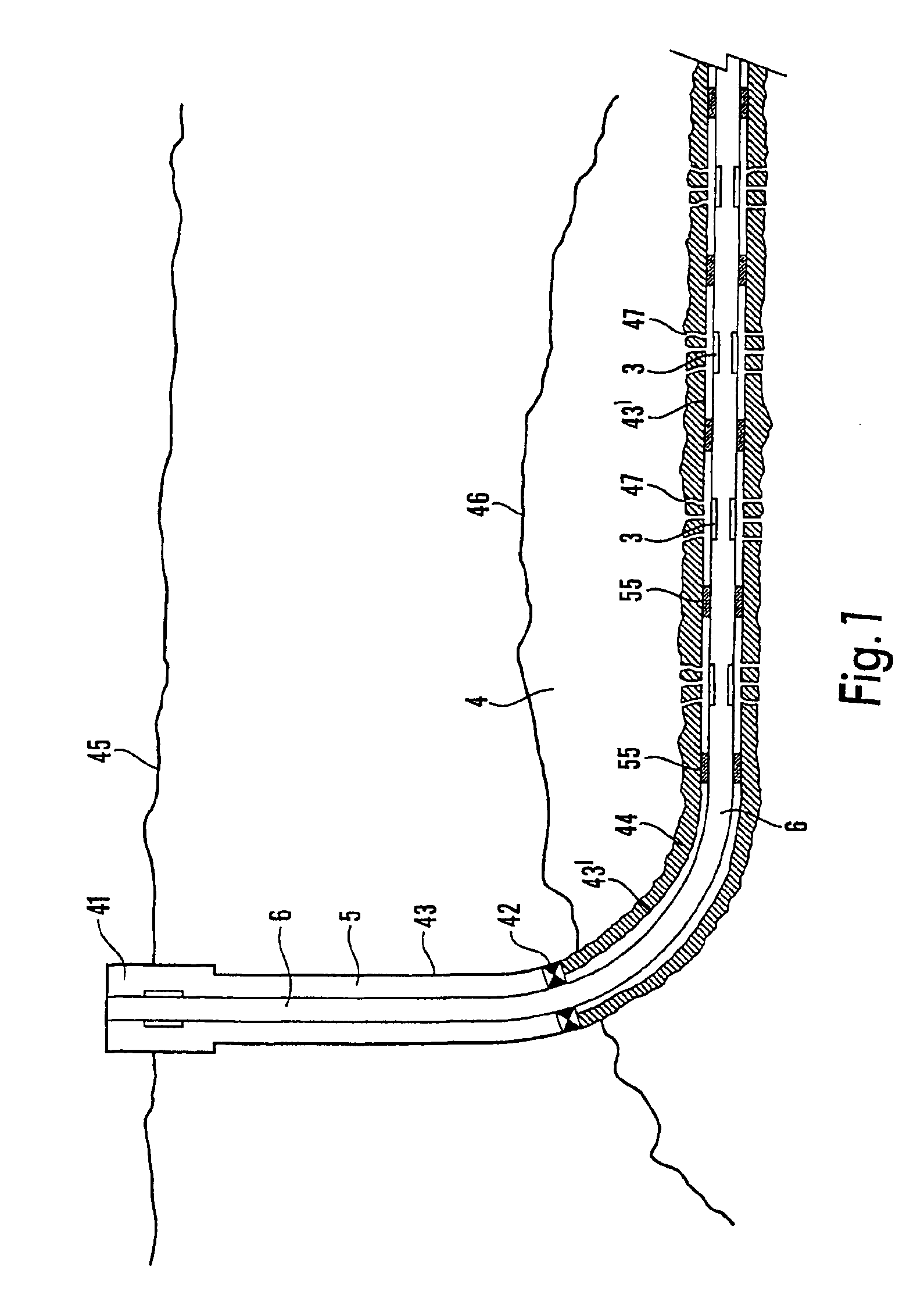
[0036]A well 5 has been drilled from the seabed 45 down to and into the hydrocarbon reservoir 4. The part of the well 5 that is outside the reservoir 4 is lined with a casing 43, and inside the well the reservoir is lined with a casing 43′ in order to prevent the well 5 from caving in. The space between the wall of the drilled well and the casing 43′ inside the reservoir 4 is filled with concrete 44. Disposed within the casing is a tubing 6 that extends from a wellhead 41 on the seabed 45 into the reservoir 4. Perforations 47 in the concrete 44, which perforations can be made by firing projectiles through the concrete, permit fluids in the reservoir 4 to flow through the concrete 44 and the wall of the casing 43′ and into the space between the casing 43′ and the tubing 6. A production packer 42 disposed between the casing 43′ and the tubing 6 prevents fluids in the reservoir 4 from flowing up in the well 5 between the casing 43 and the tubing 6.

[0037]The production conditions in the...


PUM


Abstract

A sleeve valve for fluid flow between a hydrocarbon reservoir and a well includes a first sleeve and a second sleeve which are relatively movable between a first position in which at least one opening in the first sleeve is aligned or misaligned with at least one opening in the second sleeve in order to admit or shut off the fluid flow. The first sleeve is provided with a radially movable sealing element that has a sealing surface adapted to rest against the second sleeve around the second sleeve opening, and at least one tension element presses the sealing element with its sealing surface against the second sleeve. A method for the assembly of such a sleeve valve includes a sealing element and a tension element placed in the outer sleeve opening and a clamping tool is adapted to the opening in the sealing element and moved outwards together with the sealing element until the sealing element is flush with the inner surface of the outer sleeve. Thereafter, the inner sleeve is inserted into the outer sleeve and the sealing element is allowed to rest against the inner sleeve and the clamping tool is removed.

Description

[0001]This is a nationalization of PCT / NO01 / 00477, filed Nov. 30, 2001 and published in English.FIELD OF THE INVENTION[0002]The invention relates to a sleeve valve for controlling fluid flow between a hydrocarbon reservoir and a tubing in a well in the hydrocarbon reservoir, where the sleeve valve comprises a first sleeve and a second sleeve that are coaxial and which by means of an actuator or a tool are relatively movable between positions where at least one opening in the first sleeve is aligned or misaligned with at least one opening in the second sleeve in order to admit or shut off the fluid flow.[0003]The invention also relates to a method for the assembly of a sleeve valve comprising a first sleeve in the form of an outer sleeve and a second sleeve in the form of an inner sleeve, where the outer sleeve and the inner sleeve are produced separately.BACKGROUND OF THE INVENTION[0004]In the recovery of hydrocarbons from hydrocarbon reservoirs, wells are drilled from the seabed or...

Claims


Application Information

Patent Timeline
IPC IPC(8): E21B34/06E21B34/00E21B34/14E21B43/12F16K3/24F16K3/00
CPCE21B34/06E21B34/14E21B43/12F16K3/243
Inventor HAUGHOM, PER OLAVNILSEN, RUNE
Owner WELL INNOVATION ENG
Why Eureka
Try Eureka