Conductive rivet for circuit card

a technology of conductive rivets and circuit cards, applied in the field of fasteners, to achieve the effect of improving electrical conductivity

Inactive Publication Date: 2005-10-04
UNITED STATES OF AMERICA THE AS REPRESENTED BY THE SEC OF THE ARMY
View PDF21 Cites 14 Cited by
  • Summary
  • Abstract
  • Description
  • Claims
  • Application Information

AI Technical Summary

Benefits of technology

[0005]The improved rivet structure of the present invention provides improved electrical conductivity between the surfaces of a metallic circuit card while at the same time electrically isolating the rivet from the ...

Problems solved by technology

The outer diameter of the insulating washer is adapted to fit within the inner diameter of the annular member and has a thickn...

Method used


Image

  • Conductive rivet for circuit card
  • Conductive rivet for circuit card

Examples


Embodiment Construction

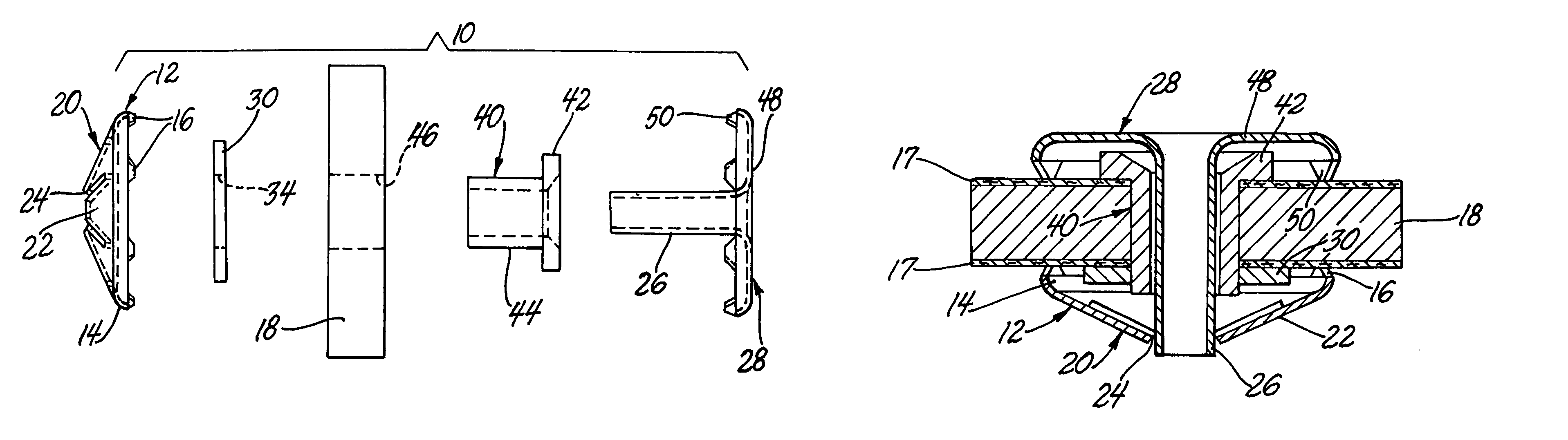
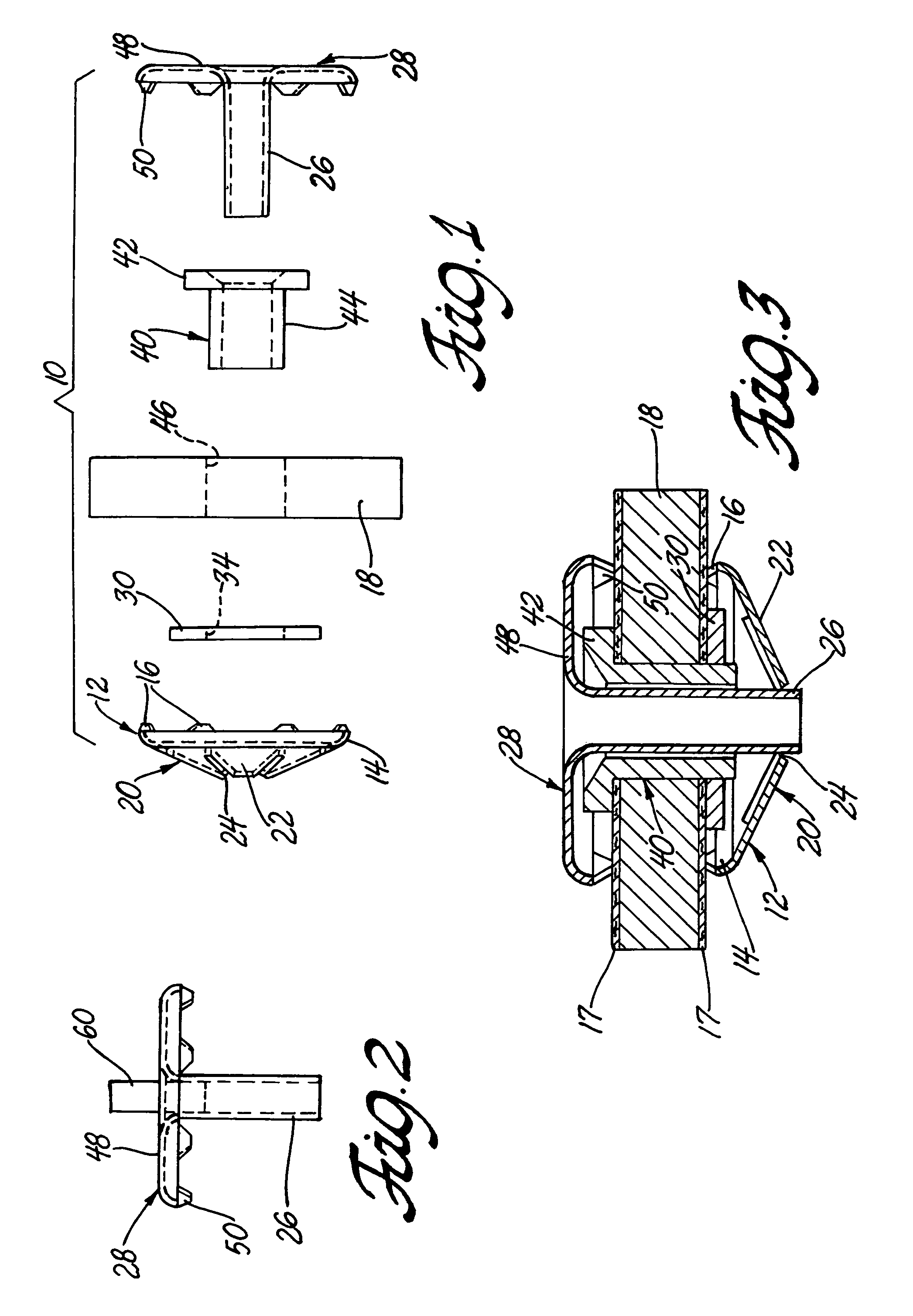
[0014]Referring to the accompanying drawing in which like numerals refer to like parts and initially FIG. 1, the rivet structure of this invention 10 has a conical structure designated generally 12 formed with an outer annular member 14. Annular member 14 has a first plurality of projections 16 which are spaced equidistant from each other about the periphery of the conical structure 12. Projections 16 are formed so that they will make good electrical and heat conductivity contact with a conductive surface 17 on circuit board 18 when the conical structure 12 is brought into contact with the conductive surface.

[0015]The conical structure 12 has a segmented disc generally 20 formed as shown from a plurality of segments 22, there being six segments in the structure shown. The segments 22 are joined together at their outer diameter to the inner diameter of the annular member 14. The segments 22 project at an angle to a plane defined by the annular member 14, to form frustoconical structu...


PUM


Abstract

The conductive rivet designed to connect the first and second conducting surfaces of circuit board through an aperture in the board. The rivet includes a conical member with an associated insulating washer associated on one side of circuit board. A T-shaped rivet and cooperating insulating sleeve are designed to contact the opposite side of the circuit board and provide a thermal conduction path via tail on the T-shaped rivet to the conical member on the opposing side.

Description

GOVERNMENT INTEREST[0001]This invention can be made used and licensed by the United Sates for Governmental Purposes without payment to me of any royalty.BACKGROUND OF THE INVENTION[0002]In one aspect this invention relates to fasteners for attaching items to a substrate. In a further aspect, this invention relates to coated, metallic circuit cards and means to conduct current from one surface coating to the opposite face and not diminish any thermal transfer.[0003]Heat is a particularly destructive condition for circuit card components. In certain applications, particularly in military vehicles and more especially combat vehicles, there is severely limited space for air flow and the vehicles are also subjected to extreme environmental heat under many combat conditions. Failure of a particular card can result in mission failure and death to vehicle users. To combat this problem, the military may use specialized metallic circuit cards that are engineered to enhance heat dissipation. S...

Claims


Application Information

Patent Timeline
IPC IPC(8): H01R12/00H01R4/06H01R12/16
CPCH01R4/06H01R12/523H01R12/7082H01R12/526
Inventor HANSEN, DAVID N.
Owner UNITED STATES OF AMERICA THE AS REPRESENTED BY THE SEC OF THE ARMY
Why Eureka
Try Eureka