Hybrid ozone generator

Inactive Publication Date: 2005-10-04
BARNES RONALD L
View PDF3 Cites 21 Cited by
  • Summary
  • Abstract
  • Description
  • Claims
  • Application Information

AI Technical Summary

Benefits of technology

[0005]This invention is a hybrid ozone generator that utilizes ultraviolet light from a cold or hot cathode lamp to produce ozone. An electrical field is disposed around the lamp, the electrical field pumping energy into oxygen flowing past the lamp. In addition, a theta pinch

Problems solved by technology

In addition, a theta pinch is performed on the plasma in t

Method used


Image

  • Hybrid ozone generator
  • Hybrid ozone generator
  • Hybrid ozone generator

Examples


Example

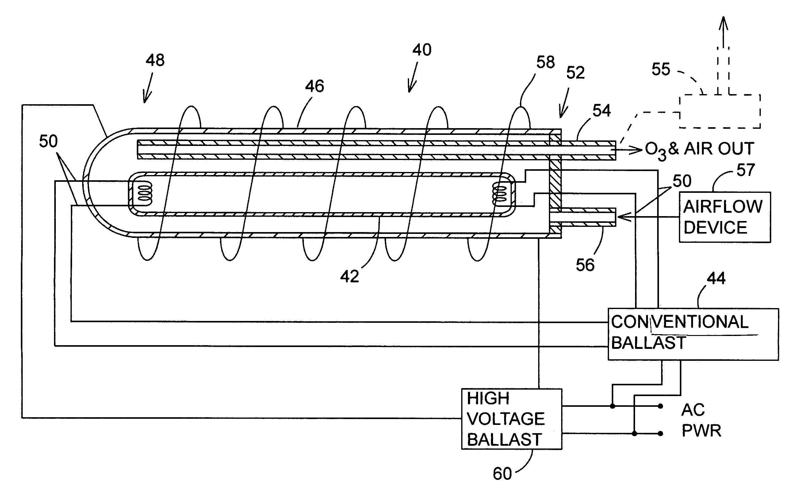
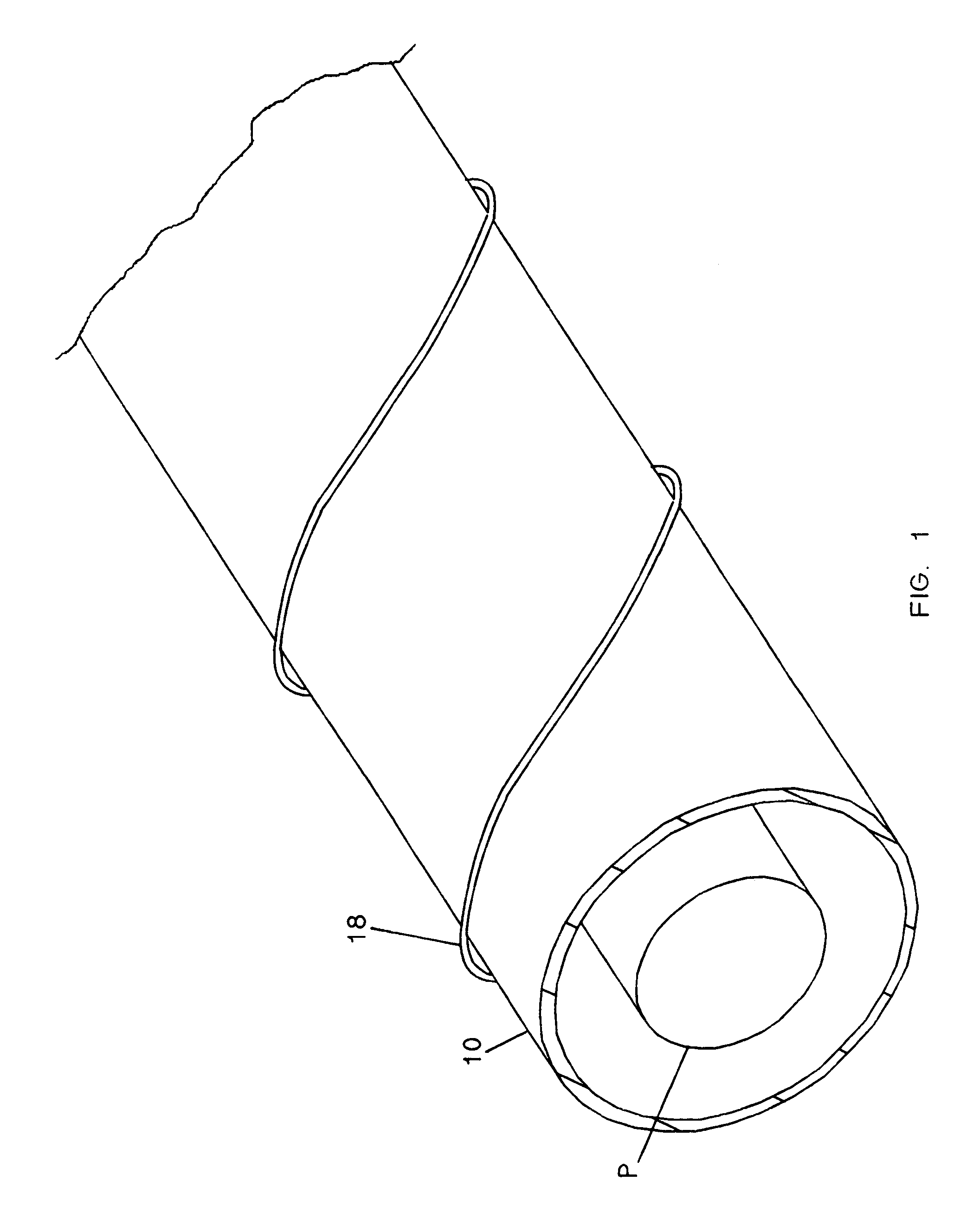
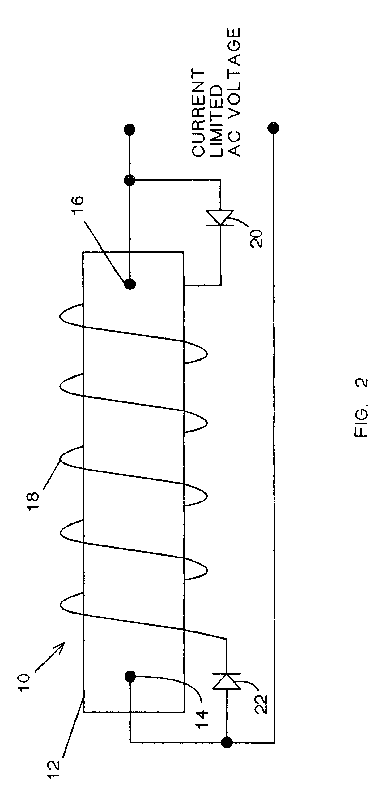
DETAILED DESCRIPTION OF THE DRAWINGS

[0013]In a conventional mercury plasma tube used to generate ozone, mercury gas, in conjunction with small amounts of pening gasses such as neon and argon used to initiate the ionization upon energizing the tube, becomes a plasma and conducts electrons from end-to-end and across the width between the inner walls of the lamp. As stated, electrons in the plasma impinge inner surfaces of these walls, heating the walls and contributing to overall losses in the system. In order to increase efficiency of these ozone-generating lamps, Applicant provides an ozone generator of the ultra-violet type wherein the plasma containment lamp or lamps are substantially surrounded by magnetic and electrical fields that causes plasma to be repelled from walls of the lamp and electrons in the plasma to be accelerated. Such fields, when properly oriented, increase luminescence of the mercury plasma in the ultraviolet spectral ranges, thereby causing increased disassoci...


PUM


Abstract

An ozone generator utilizing an ultraviolet light tube for generating ozone is disclosed. In this ozone generator, efficiency in converting oxygen to ozone is increased by imposing an electrical field around the light tube. This electrical field causes a theta pinch in the plasma of the light tube, increasing luminescence in the ultraviolet spectral range and exciting diatomic oxygen molecules passing through the electrical field. Thus excited, the diatomic oxygen is easier to disassociate and become converted to ozone.

Description

CROSS REFERENCE TO RELATED APPLICATIONS[0001]This application is a continuation-in-part of patent application Ser. No. 09 / 717,904, filed Nov. 20, 2000, now U.S. Pat. No. 6,426,053, and which claims the benefit of provisional application No. 60 / 166,255, filed Nov. 18, 1999.FIELD OF THE INVENTION[0002]This invention relates to ozone generators, and particularly to an ozone generator using a hot cathode tube wherein efficiency of the generator is increased by exciting oxygen flowing past the tube and mercury plasma within the tube is electromagnetically pinched in order to increase efficiency of the ozone generator.BACKGROUND OF THE INVENTION[0003]Ozone generators utilizing mercury plasma tubes are well known. In these ozone generators, a transparent containment tube similar to a conventional fluorescent tube contains a mercury gas that when ionized by an electrical potential, becomes an electrically conductive plasma. This plasma emits ultraviolet light at one wavelength, 185 nanomete...

Claims


Application Information

Patent Timeline
IPC IPC(8): C01B13/10C01B13/11
CPCC01B13/10C01B13/11C01B2201/22C01B2201/82
Inventor BARNES, RONALD L.
Owner BARNES RONALD L
Why Eureka
Try Eureka