Pointing device

a pointing device and pointing technology, applied in the direction of mechanical control devices, manual control with single controlling member, instruments, etc., can solve the problems of further deteriorating operational properties, difficulty in ensuring a space for operating a mouse having a normal structure, and difficulty in the proper and stable operation of the operating part, so as to reduce the height of the assembled pointing device

Inactive Publication Date: 2005-10-04
FUJITSU COMPONENENT LTD
View PDF12 Cites 68 Cited by
  • Summary
  • Abstract
  • Description
  • Claims
  • Application Information

AI Technical Summary

Benefits of technology

[0010]It is therefore an object of the present invention to provide a pointing device having a magneto-electro transducer, i

Problems solved by technology

Incidentally, the built-in type pointing device as described above essentially imposes an input operation within a limited area on a operator, and besides, there is a possibility of further deteriorating the operational properties when the height reduction is facilitated.
In particular, when the data processor is used in a portable way, it is difficult to ensure a space for operating a mouse having a normal structure, in which an operative ball is partially exposed on the back side of the mouse.
However, if the dimension in a vertical direction of the elastic member, generally formed by a rubber or a coil spring for biasing the operating part toward the initial position, is excessively reduced, it is possible that a spring force generated when the elastic member is elastically deformed becomes in

Method used


Image

  • Pointing device
  • Pointing device
  • Pointing device

Examples


Embodiment Construction

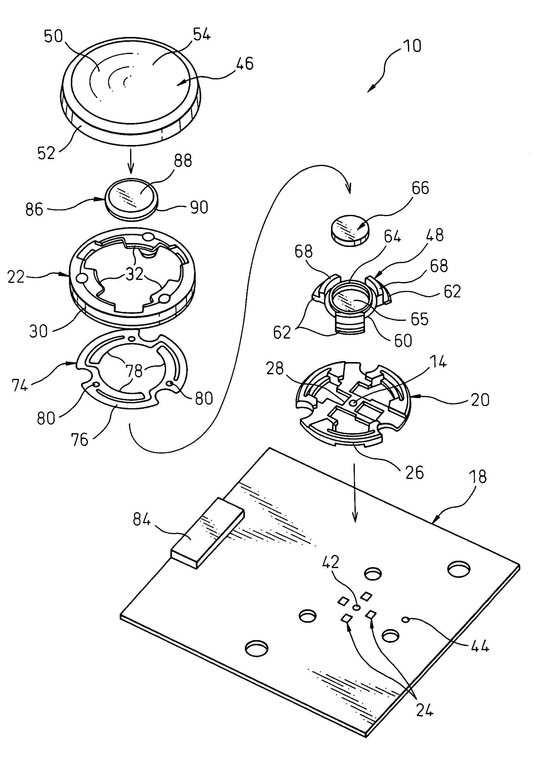
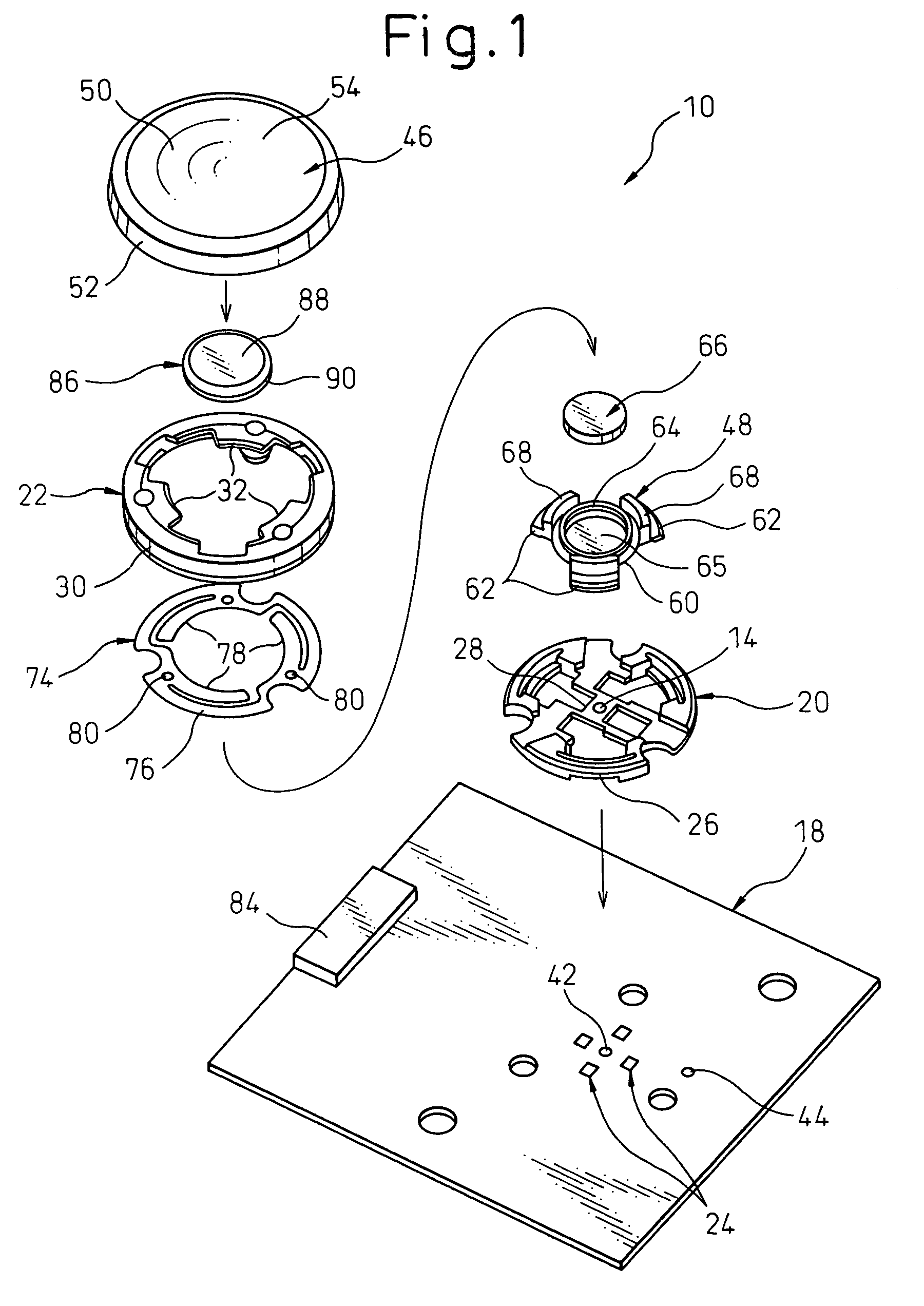
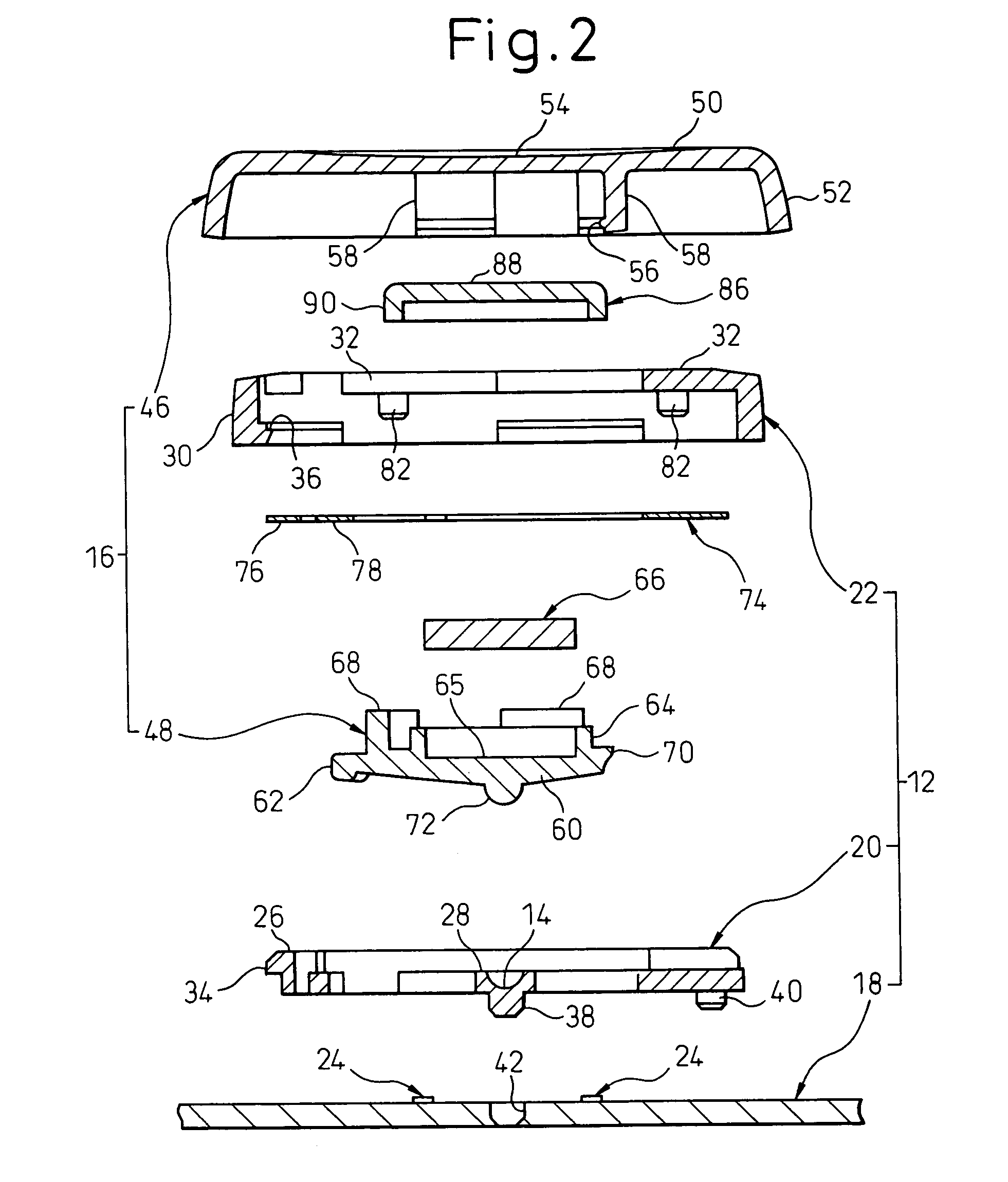
[0042]Referring to the drawings, wherein the same or similar components are denoted by common reference numerals, FIGS. 1 to 4 show a pointing device 10 according to one embodiment of the present invention. The pointing device 10 can be suitably and advantageously used as an auxiliary input device having a reduced height for indicating coordinate data on a display incorporated in a data processor, particularly in a portable small-sized data processor, such as a personal computer, a personal word processor, and so on.

[0043]The pointing device 10 includes a base part 12 and an operating part 16 supported on the base part 12 and rockable about a fulcrum 14 provided on the base part 12. The base part 12 includes a circuit board 18 onto which electronical elements, such as a CPU (not shown), are mounted, and first and second frame members 20, 22 fixedly attached in a mutually assembled state to the circuit board 18. A plurality (four, in the illustrated embodiment) of magneto-electro tra...


PUM


Abstract

A pointing device including a base part, an operating part supported on the base part in a rockable manner about a fulcrum, a magnet carried on the operating part, a magneto-electro transducer carried on the base part, and an elastic member arranged between the base part and the operating part to elastically push the operating part toward an initial balanced position on the base part. The elastic member is formed as a plate spring provided with a first section engageable with the base part and a second section engageable with the operating part. The second section is integrally joined to the first section and located to extend around the fulcrum. The first section of the plate spring extends annularly around the fulcrum and is fixedly supported on the base part, and the second section extends arcuately along the first section to exert a spring action.

Description

BACKGROUND OF THE INVENTION[0001]1. Field of the Invention[0002]The present invention relates to a pointing device which can be suitably provided in a data processor such as a personal computer.[0003]2. Description of the Related Art[0004]In a digital data processor, such as a personal computer, provided with a display and a keyboard incorporated therein, a pointing device is conventionally used as an auxiliary input device for indicating coordinate data on the display by entering analog information through a manual operation by an operator. Particularly, a typical small-sized portable data processor is provided with a built-in type pointing device integrally incorporated in a housing body of the data processor, or otherwise a separate pointing device, such as a mouse, is detachably connected with the processor housing body through a cable and a connector when it is used.[0005]The conventional pointing device, described, e.g., in Japanese Unexamined Patent Publication (Kokai) No. 10...

Claims


Application Information

Patent Timeline
IPC IPC(8): G06F3/033G09G5/08G06F3/0338G05G9/047
CPCG06F3/0338G05G2009/04755
Inventor NAKAMURA, SHUJIKOIKE, TAMOTSU
Owner FUJITSU COMPONENENT LTD
Why Eureka
Try Eureka