Optical correlation device and method

Active Publication Date: 2005-10-04
THE OHIO STATES UNIV
View PDF2 Cites 19 Cited by
  • Summary
  • Abstract
  • Description
  • Claims
  • Application Information

AI Technical Summary

Benefits of technology

[0011]The following presents a simplified summary of apparatus, systems and methods associated with an optical correlator to facilitate providing a basic understanding of these items. This summary is not an extensive overview and is not intended to

Problems solved by technology

Thus it becomes difficult to implement a large number of them.
One such disadvantage is that each fiber splitter results in some insertion lo

Method used


Image

  • Optical correlation device and method
  • Optical correlation device and method
  • Optical correlation device and method

Examples


Example

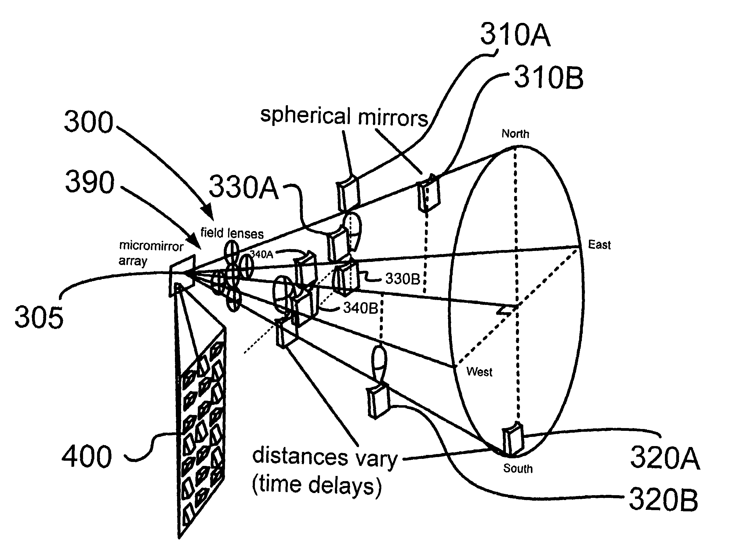
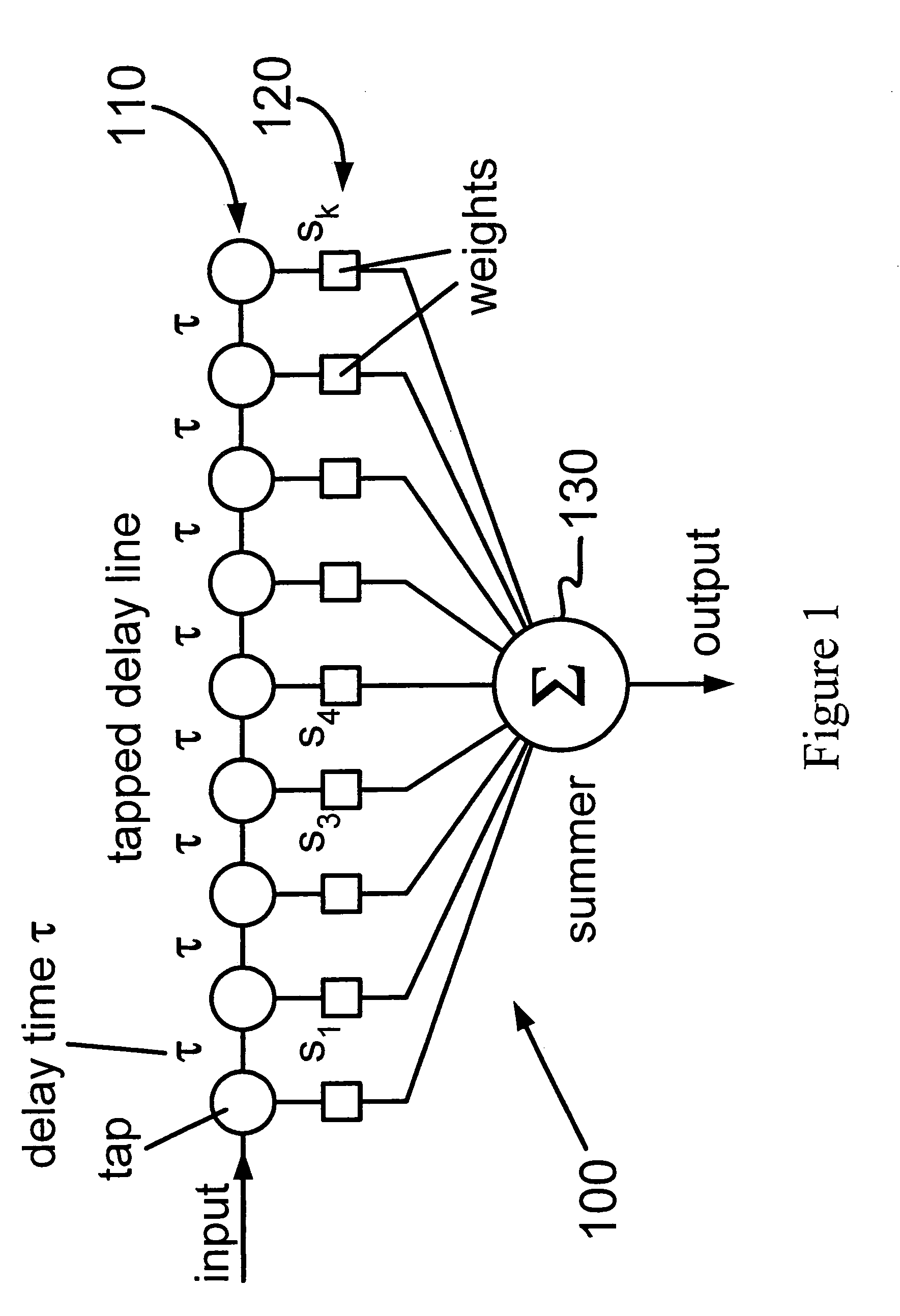
[0020]One advantage of performing correlations optically rather than electronically is the increased speed of optical correlation. In an electronic correlator, the taps and delays and controlled by circuits, whose ultimate speed is limited to the fastest existing electronics. To implement delays optically, however, one need only vary the path length. Thus the time between samples can be arbitrarily small. In fact, one can produce hundreds or thousands of optical pulses during a single electronic bit. Note that the weighting and summing are also done optically; thus the entire correlation signal, a calculation involving these thousands of optical pulses, can be produced during a time that is also small compared to electronic switching speeds.

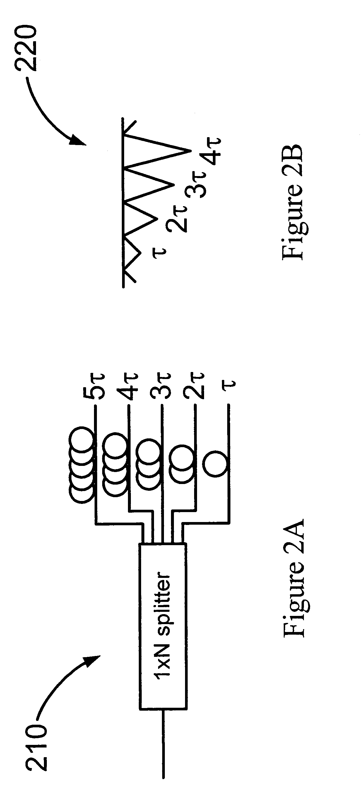
[0021]To produce ultra-short time delays using the fiber approaches of prior art optical correlators 210 and 220, however, requires an extremely precise cutting of fibers to appropriate lengths. Such approaches further require cutting very short ...


PUM


Abstract

A temporal optical correlator is disclosed. The example optical correlator includes a light source, a set of White cells and a micro-mirror array. The micro-mirror array and set of White cells cooperate to produce a correlated summed output signal. A method for processing signals using the example optical correlator is also disclosed.

Description

CROSS-REFERENCE TO RELATED APPLICATION[0001]This application claims priority to U.S. Provisional Application entitled “Optical Correlation Device and Method,” Ser. No. 60 / 430,207, filed Dec. 2, 2002, which is incorporated herein by reference in its entirety. The present application is further related to contemporaneously filed U.S. Non-Provisional Applications entitled “Method and Apparatus for Combining Optical Beams” and “Method and Apparatus for Monitoring the Quality of Optical Links”, based on U.S. Provisional Application Ser. Nos. 60 / 430,213 filed on Dec. 2, 2002 and Ser. No. 60 / 430,214 filed on Dec. 2, 2002 respectively, each of which is incorporated herein by reference in its entirety.TECHNICAL FIELD[0002]The devices, methods and systems described herein relate generally to optical correlation and more particularly to temporal optical correlation.BACKGROUND[0003]Optical correlators fall into two main categories, spatial correlators, which are well known, and temporal correla...

Claims


Application Information

Patent Timeline
IPC IPC(8): G02B26/08G06E3/00
CPCG06E3/00
Inventor ANDERSON, BETTY LISE
Owner THE OHIO STATES UNIV
Why Eureka
Try Eureka