Single stage PFC power converter

a power converter and single-stage technology, applied in the field of power converters, can solve the problems of reducing the efficiency increasing the cost and device counts of the power converter, etc., and achieve the effect of reducing the output ripple nois

Active Publication Date: 2005-10-04
SEMICON COMPONENTS IND LLC
View PDF7 Cites 51 Cited by
  • Summary
  • Abstract
  • Description
  • Claims
  • Application Information

AI Technical Summary

Benefits of technology

The present invention provides a single stage power factor correction (PFC) power converter that performs a PFC function to a half-bridge flyback power converter. The converter includes a transformer and a secondary circuit. The transformer has a primary winding coupled to a high side switch and a low-side switch in series, and a secondary winding coupled to a secondary circuit. The high-side and low-side switches periodically couple an input voltage to the primary winding of the transformer. The energy stored in the transformer is transmitted to the secondary circuit when the switches are switched off. The energy is charged to a bulk capacitor through a flyback diode and a second flyback diode. The bulk capacitor is used to power the secondary circuit when the input voltage is lower than the voltage across the bulk capacitor, reducing output ripple noise. The converter performs the PFC function using a forward diode and a forward inductor to forward the energy of the bulk capacitor to the flowing path of the input voltage.

Problems solved by technology

The technical problem addressed in this patent is to develop a single stage power converter with PFC function that is more efficient, cost-effective, and has reduced output ripple noise and higher reliability. The invention achieves this by integrating a PFC stage with a second stage power converter that includes a transistor, a transformer, and secondary circuitry to regulate output voltage and reduce ripple noise.

Method used


Image

  • Single stage PFC power converter
  • Single stage PFC power converter
  • Single stage PFC power converter

Examples


Embodiment Construction

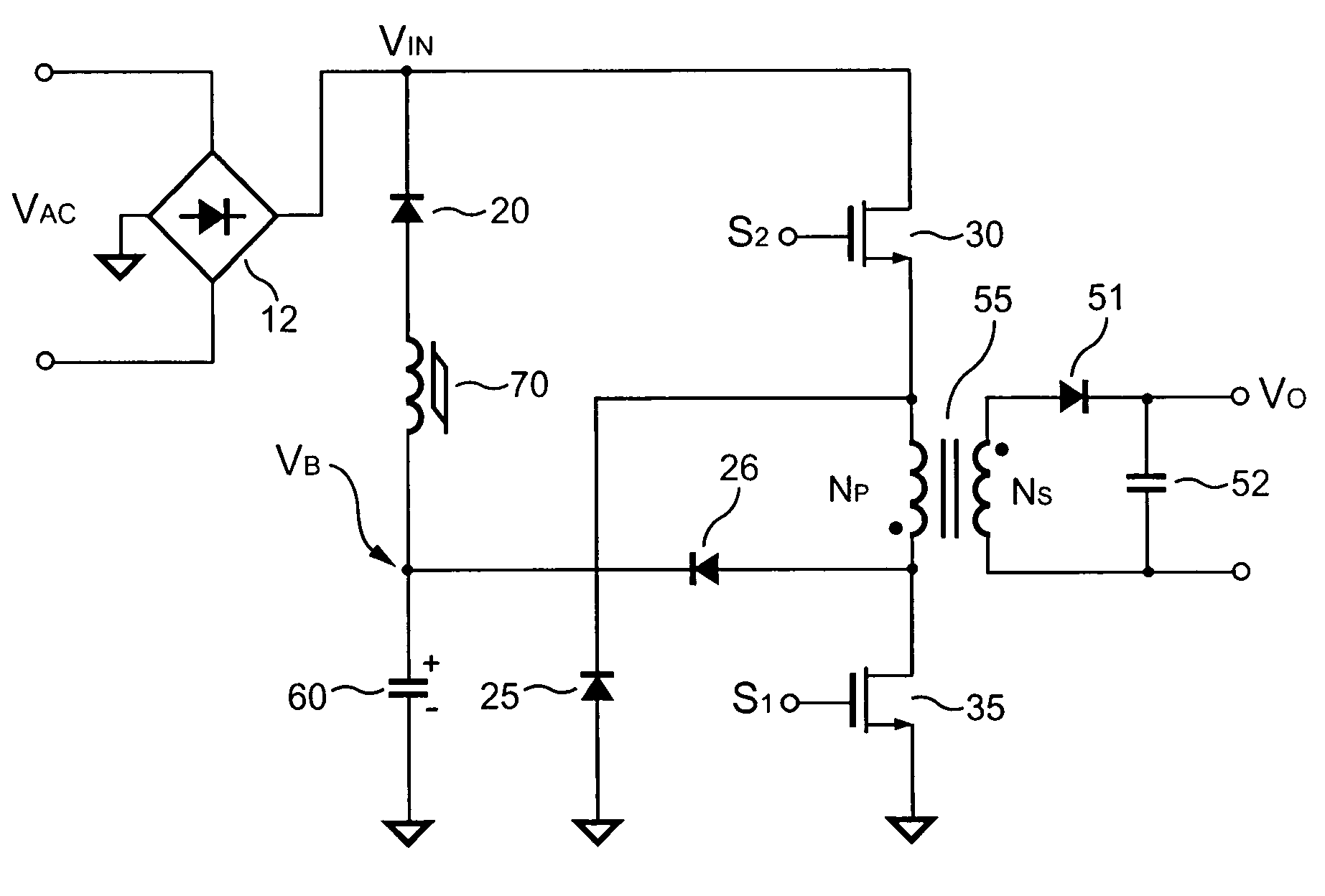
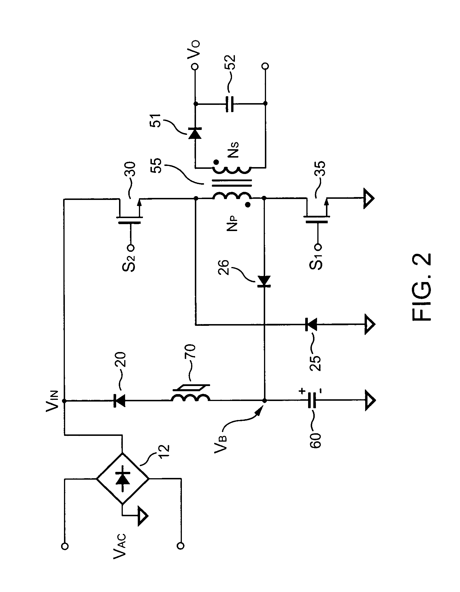
[0014]Referring to FIG. 2, a single stage power factor correction (PFC) power converter according to an embodiment of the present invention is illustrated. The single stage PFC power converter includes a transformer 55 having a primary winding NP, a secondary winding NS, a secondary circuit, a high-side switch 30, a low-side switch 35, flyback diodes 25 and 26, a forward diode 20, a bulk capacitor 60, a forward inductor 70, and a bridge rectifier 12. The bridge rectifier 12 rectifies an AC line voltage VAC to an input voltage VIN. A first terminal of the high-side switch 30 is supplied with the input voltage VIN. A second terminal of the high-side switch 30 is connected to a second terminal of the primary winding NP. A first terminal of the primary winding NP is coupled to a first terminal of the low-side switch 35. A second terminal of the low-side switch 35 is coupled to a ground reference level. The secondary winding NS of the transformer 55 is coupled to the secondary circuit. T...


PUM


Abstract

A single stage PFC power converter is provided for performing a PFC function in a half-bridge flyback power converter. A high-side switch and a low-side switch periodically supply an input voltage to a primary winding of a transformer. When the high-side switch and low-side switch are switched off, the energy stored in the transformer will be transmitted to a secondary circuit and charged to a bulk capacitor. The bulk capacitor serves to recycle the energy and reduce the output ripple noise. A forward diode and a forward inductor serve to forward the energy of the bulk capacitor to the flowing path of the input voltage for performing PFC function.

Description


Claims


Application Information

Patent Timeline
Owner SEMICON COMPONENTS IND LLC
Why Eureka
Try Eureka