Method, system, storage medium and server apparatus for controlling workflow

a workflow and workflow technology, applied in the field of workflow control system, can solve the problems of insufficient merely passive input from participants, complex, unrealistic representation of individual participants, etc., and achieve the effect of flexible addressing changes in workflows

Inactive Publication Date: 2005-10-04
IBM CORP
View PDF7 Cites 20 Cited by
  • Summary
  • Abstract
  • Description
  • Claims
  • Application Information

AI Technical Summary

Benefits of technology

[0008]Another object to be attained by the present invention is to provide a workflow controlling system

Problems solved by technology

Especially, where it is not necessary to fix a flow of documents in advance (or not desired to do so), quite a few kinds of paths exist, and it is not realistic to represent them individually.
To cope with such variations, however, descriptions corresponding

Method used


Image

  • Method, system, storage medium and server apparatus for controlling workflow
  • Method, system, storage medium and server apparatus for controlling workflow
  • Method, system, storage medium and server apparatus for controlling workflow

Examples


Embodiment Construction

4.1 Outline of the Invention

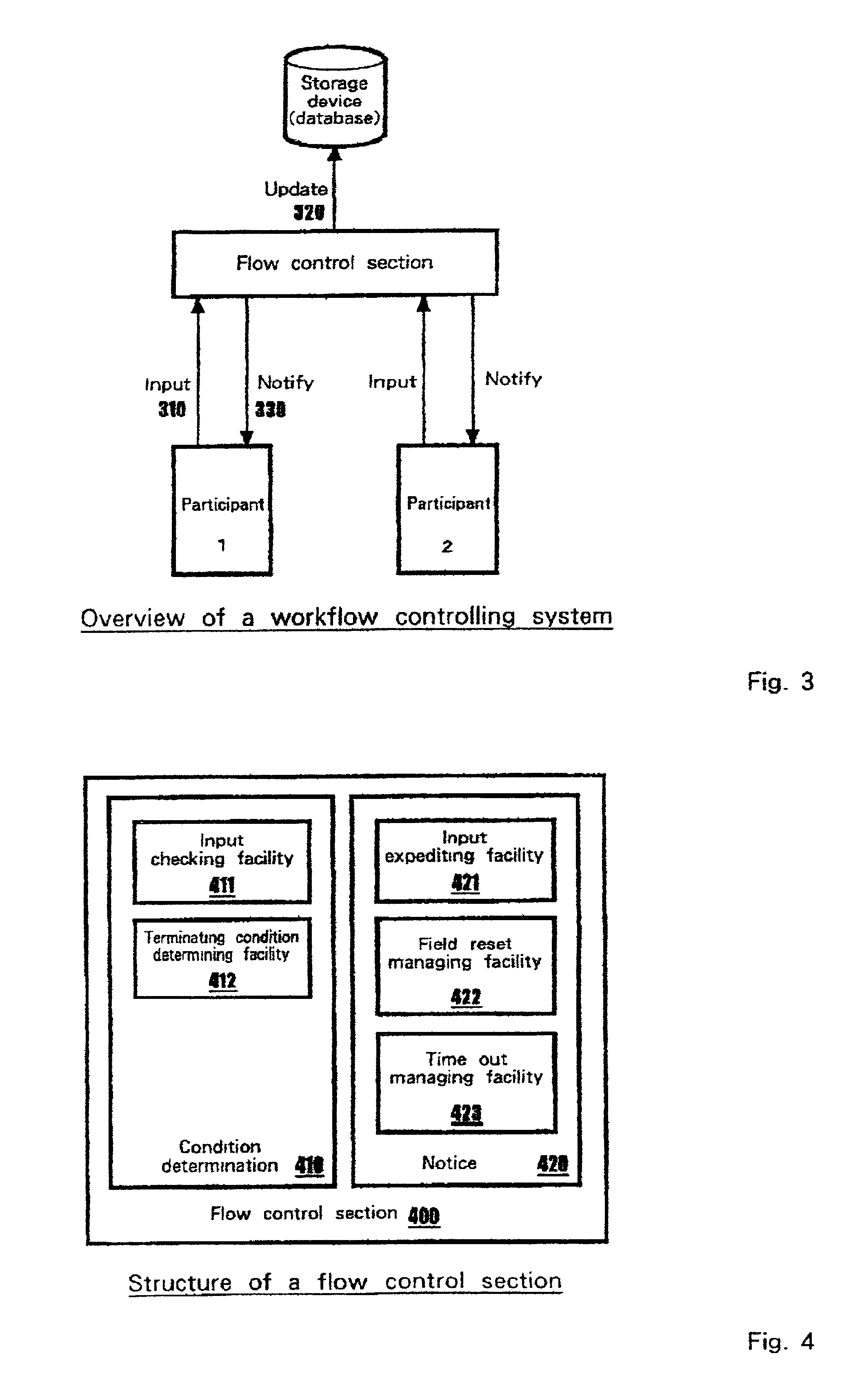
[0046]The present invention provides a method of using a declarative description for describing a flow so as to keep it unfixed. As mentioned later, this method takes an approach wherein a document including every field appearing in a series of flows is defined as logical including data and rules, and constraints on fields therein are described. Thus, participants can make any change at any time as long as the constraints are met, and consequently various flows become possible, and besides, any change of a workflow definition can be flexibly handled.

[0047]Namely, as mentioned above, while the conventional method by descriptive programming describes flows of documents themselves explicitly by a program, the present invention covers a method wherein a declarative description including data and rules is converted into a logic program, as to constraints on fields in a document or dependencies among fields, so as to dynamically control flows. A method based on...


PUM


Abstract

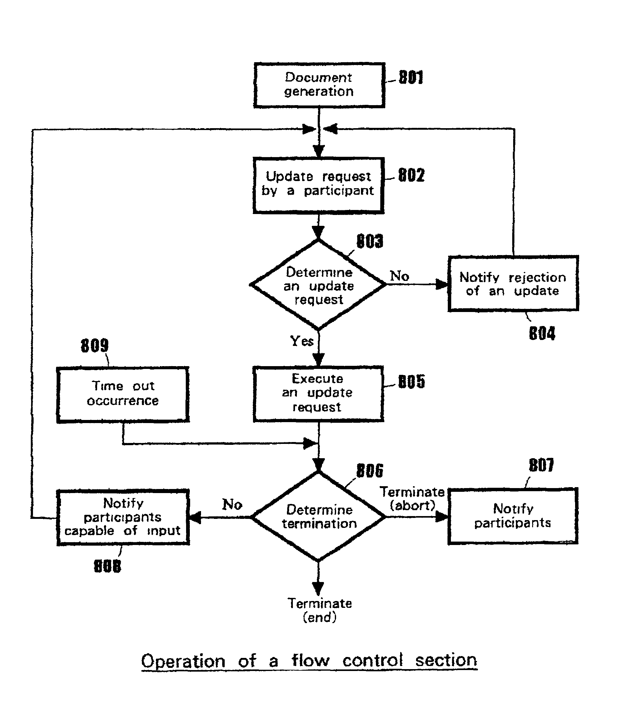
Flow control for a workflow controlling system is achieved wherein a business document flows among a plurality of participants by, at a system which includes a server apparatus including a storage device and terminal apparatus connecting to the server apparatus via a network, generating a document which includes data and rules responding to a request from one of the terminal apparatus and storing it in the storage device, receiving an update request on the document from the first terminal apparatus, determining whether the update request is appropriate or not, and if the update request is appropriate then executing the update on the document, and determining whether the workflow/process was completed or not, and if not completed then identifying the second terminal apparatus which can update next and notifying it.

Description

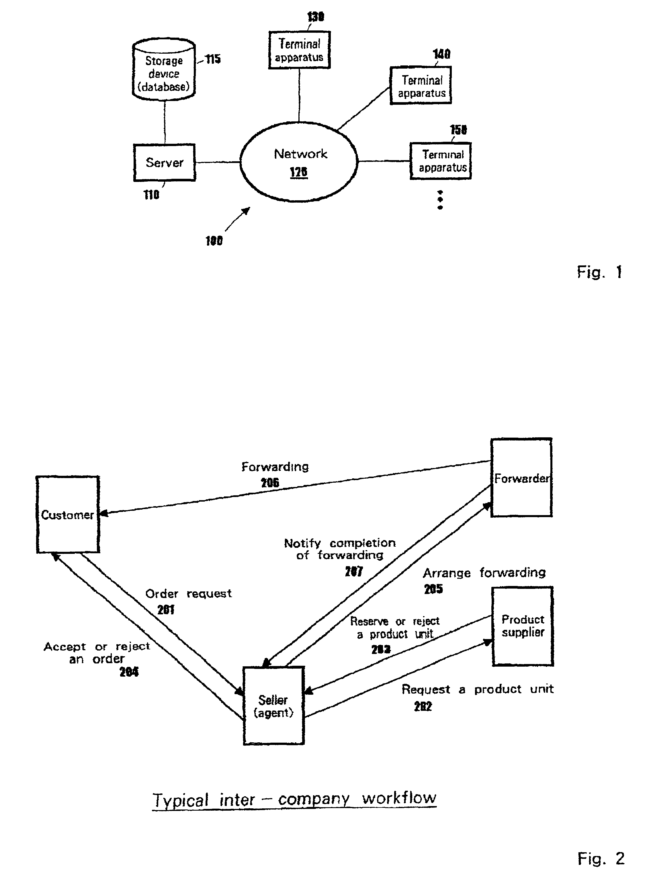
DESCRIPTION[0001]1. Field of the Invention[0002]The present invention relates to a workflow controlling system in which documents flow among a plurality of participants, in particular covering a flow control section that is a central component thereof.[0003]2. Related Art[0004]FIG. 2 shows an example of a typical inter-company workflow that is a subject of the present invention. First, a customer makes an order request (201), and a seller requests a product supplier to reserve a specific product unit and receives the response (202, 203). Next, the customer is informed of whether the reservation is confirmed or not (204), and then arranges forwarding with a forwarder (205). Subsequently, the forwarder advises the customer of a forwarding date (206), and notifies the seller when the forwarding is completed (207).[0005]When developing an application based on such a workflow, in the case of the conventional method, an application developer would define individual documents as data, and ...

Claims


Application Information

Patent Timeline
IPC IPC(8): G06Q10/00H04L29/08H04L29/06G06Q10/06G06Q10/10G06Q50/00
CPCG06Q10/10H04L69/329H04L67/42H04L67/01
Inventor NAKAMURA, YUHICHINEYAMA, RYOHSEKI, NAISHINKAJITANI, KOHICHI
Owner IBM CORP
Why Eureka
Try Eureka