Rankine cycle apparatus

a technology of cycle apparatus and cylinder, which is applied in mechanical apparatus, machines/engines, separation processes, etc., to achieve the effect of reducing variation in the respective heat transmitting area and reducing unwanted cavitation

Inactive Publication Date: 2005-10-11
HONDA MOTOR CO LTD
View PDF10 Cites 9 Cited by
  • Summary
  • Abstract
  • Description
  • Claims
  • Application Information

AI Technical Summary

Benefits of technology

[0028]In this way, the present invention can provide a novel automatic working medium supply system which is capable of collecting and storing the working medium leaked or discharged out of the closed working medium circulation circuit and also re-supplying a deficient amount of the working medium to the circulation circuit. Further, the automatic working medium supply system provided by the invention can be of a significantly simplified structure and reduced size.
[0029]In the Rankine cycle apparatus of the present invention, the open (i.e., open-to-atmospheric-air) tank is provided separately from the conventional sealed tank in the working medium circulation circuit, and a portion of the working medium, let out from the circulation circuit, is collected and stored in the open tank in the liquid-phase state. Further, a deficient amount of the working medium is returned or re-supplied to any point of the section (i.e., section having a pressure substantially equal to the atmospheric pressure) of the circulation circuit extending from the outlet port of the expander, via the condenser, to the suction portion of the supply pump, so that the deficient working medium can be replenished into the closed circulation circuit. In this way, the present invention can appropriately reduce a pressure difference between the open-to-atmospheric-air tank and the circulation circuit, to thereby allow the returned working medium to circulate with increased ease and smoothness. Further, the present invention can make appropriate adjustment (i.e., produce an appropriate buffer effect) on variation in the flow amount (flow rate) of the working medium within the closed circulation circuit, and allows the leaked or discharged working medium to be re-circulated through the circulation circuit easily and smoothly.
[0030]The present invention can appropriately adjust (i.e., produce an appropriate buffer effect on) variation in the flow amount of the working medium within the closed circulation circuit of the Rankine cycle apparatus, so as to appropriately absorb or accommodate the flow amount variation. Specifically, in the present invention, an optimized amount of the working medium can be circulated, on the basis of the fluid level position of the liquid-phase working medium within the condenser, by means of the supply amount, and variation in the heat transmitting areas of the gaseous-phase and liquid-phase portions of the condenser can be reduced.
[0033]Namely, in the Rankine cycle apparatus of the present invention, where the liquid level position of the liquid-phase working medium within the condenser is constantly controlled to be at the predetermined level position, the condensed water is discharged when the liquid level position within the condenser has risen above the predetermined level position, but a deficient amount of the working medium is replenished or re-supplied when the liquid level position within the condenser has fallen below the predetermined level position. Such arrangements can reduce variation in the respective heat transmitting areas of the gaseous-phase and liquid-phase portions of the condenser, so that the necessary cooling can be performed without regard to the variation in the heat transmitting areas. Further, the inventive arrangements can effectively reduce unwanted cavitations in the supply pump and consumption of extra heat energy for re-heating by the evaporator.

Problems solved by technology

Further, a deficient amount of the working medium is returned or re-supplied to any point of the section (i.e., section having a pressure substantially equal to the atmospheric pressure) of the circulation circuit extending from the outlet port of the expander, via the condenser, to the suction portion of the supply pump, so that the deficient working medium can be replenished into the closed circulation circuit.

Method used


Image

  • Rankine cycle apparatus
  • Rankine cycle apparatus
  • Rankine cycle apparatus

Examples


Embodiment Construction

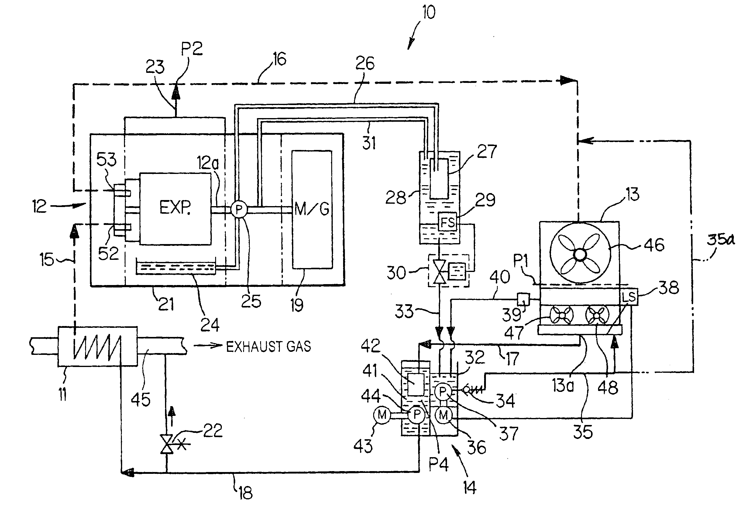
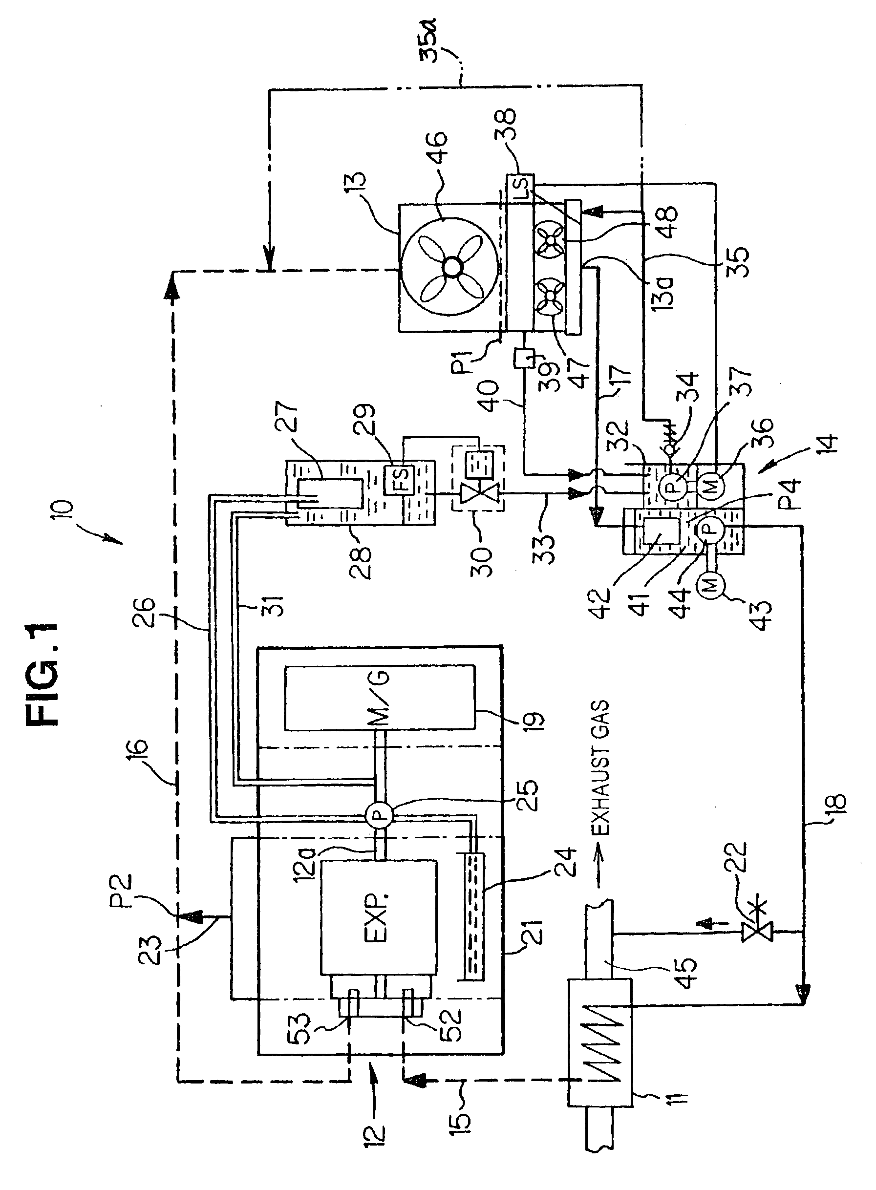
[0049]First, a description will be made about an example general setup of a Rankine cycle apparatus in accordance with an embodiment of the present invention, with reference to FIG. 1.

[0050]The Rankine cycle apparatus 10 includes an evaporator 11, an expander 12, a condenser 13, and a water supplying pump unit 14 provided with a supply pump.

[0051]The evaporator 11 and the expander 12 are interconnected via a pipe 15, and the expander 12 and the condenser 13 are interconnected via a pipe 16. Further, the condenser 13 and the water supplying pump unit 14 are interconnected via a pipe 17, and the water supplying pump unit 14 and the evaporator 11 are interconnected via a pipe 18. With such a piping structure, there is formed closed circulation circuitry (circulation system) through which a working medium is circulated within the Rankine cycle apparatus 10 in the gaseous or liquid phase. The working medium in the Rankine cycle apparatus 10 is in water (liquid) and water vapor (gaseous) ...


PUM

PropertyMeasurementUnit
temperatureaaaaaaaaaa
heat energyaaaaaaaaaa
mechanical energyaaaaaaaaaa

Abstract

Rankine cycle apparatus, having closed working medium circulation circuitry, includes a collection mechanism for collecting a working medium leaked or discharged out of the circulation circuitry. The working medium collected via the collection mechanism is stored in an open tank, and the thus-stored liquid-phase working medium is returned to a condenser by means of a return pump.

Description

[0001]This Nonprovisional application claims priority under 35 U.S.C. §119(a) on Patent Application No(s). 2003-344492 and 2003-377363 filed in Japan on Oct. 2, 2003 and Nov. 6, 2003, the entire contents of which are hereby incorporated by reference.FIELD OF THE INVENTION[0002]The present invention relates generally to Rankine cycle apparatus. More particularly, the present invention relates to an improved Rankine cycle apparatus which is used, for example, as a vehicle-mounted apparatus for converting exhaust heat energy of a vehicle-mounted engine into mechanical energy, and which includes a working medium supply system to appropriately deal with leakage of a working medium.BACKGROUND OF THE INVENTION[0003]Rankine cycle apparatus have been known as systems for converting heat energy into mechanical work. The Rankine cycle apparatus include a structure for circulating water as a working medium, in the liquid and gaseous phases within a sealed piping system forming a circulation sys...

Claims


Application Information

Patent Timeline
Patent Type & Authority Patents(United States)
IPC IPC(8): B01D5/00F01K9/00F01K23/06
CPCB01D5/0093F01K9/00F01K23/065
Inventor TSUTSUI, TOSHIHIROSEKIMOTO, KAZUYAUDA, MAKOTOTANIGUCHI, HIROYOSHI
Owner HONDA MOTOR CO LTD
Why Eureka
Try Eureka