Fuel injection valve

a technology of fuel injection valve and fuel injector, which is applied in the direction of fuel injecting pump, machine/engine, liquid transfer device, etc., can solve the problem of large overall length that the axial offset arrangement of the actuators necessitates, and achieve the effect of simple and inexpensiv

Inactive Publication Date: 2005-10-11
ROBERT BOSCH GMBH
View PDF12 Cites 15 Cited by
  • Summary
  • Abstract
  • Description
  • Claims
  • Application Information

AI Technical Summary

Benefits of technology

[0006]In contrast, the fuel injector according to the present invention, having the characterizing features of the main claim, has the advantage over the related art that conventional stack actuators, or actuators having a plurality of separated regions with compensation elements, are able to be controlled by a measuring and regulating device, in such a way that a play compensation for the temperature-related linear deformations of the actuator may be achieved in a simple and inexpensive manner, without the use of expensive INVAR materials.
[0007]In this context, it is furthermore advantageous that the separate controlling of the opening actuator and the compensation actuator may be implemented at different speeds, so that the dynamic performance of the fuel injector is not adversely affected, yet the temperature compensation may occur slowly.

Problems solved by technology

This causes problems, in particular during rapid dynamic operations, since the different materials react differently, due to the dissimilar thermal expansion coefficients.
A disadvantage of the fuel injector known from German Published Patent Application No. 199 18 976 is the large overall length that the axially offset arrangement of the actuators necessitates.

Method used


Image

  • Fuel injection valve
  • Fuel injection valve
  • Fuel injection valve

Examples


Embodiment Construction

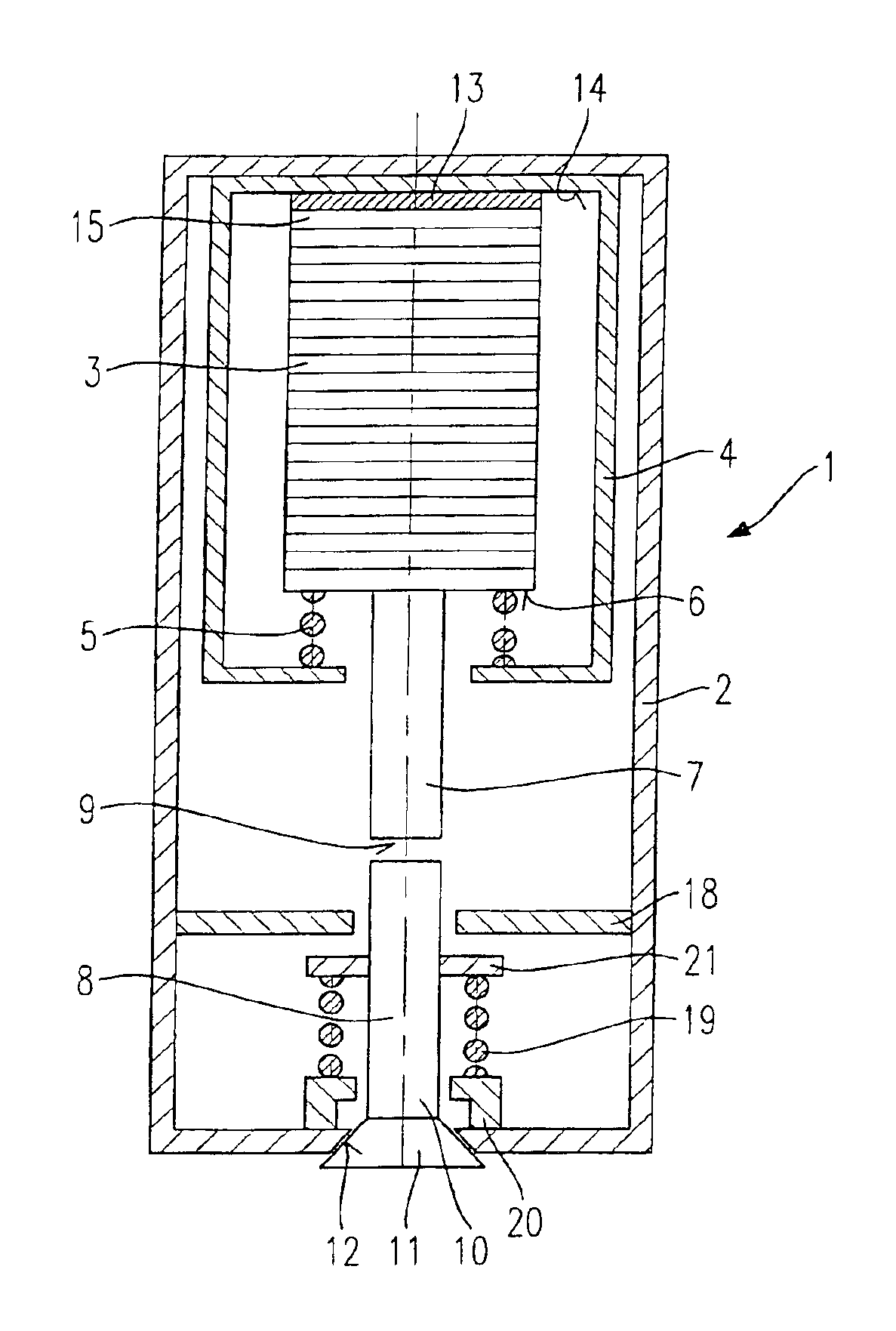
[0016]In a highly schematized sectioned view, FIG. 1A shows a longitudinal section through the essential components of a fuel injector 1 configured according to the present invention. Fuel injector 1 is embodied as a fuel injector for mixture-compressing internal combustion engines having external ignition. It is especially suited for the direct injection of fuel into a combustion chamber of an internal combustion engine.

[0017]Fuel injector 1 encompasses a housing 2 in which a piezoelectric actuator 3 is arranged. Piezoeloctric actuator 3 may be made up, for instance, of a plurality of interconnected piezoelectric layers 14. Actuator 3 is encapsulated in an actuator cartridge 4 and prestressed by a compression spring 5 clamped between actuator 3 and actuator cartridge 4. The encapsulation of actuator 3 is required to protect actuator 3 from chemical damage by the fuel. On the other hand, actuator 3, already preassembled in actuator cartridge 4, is easier to install and, in addition,...


PUM


Abstract

A fuel injector for the direct injection of fuel into a combustion chamber of an internal combustion engine includes a piezoelectric or magnetostrictive actuator and a valve-closure member able to be actuated by the actuator, the valve-closure member cooperating with a valve-seat surface to form a sealing seat, a compensation gap being present in an actuation path between the actuator and the valve-closure member. A measuring element is provided in the actuator and / or in the actuation path, the measuring element measuring the forces exerted by the actuator the valve-closure member and the actuator being regulated in such a way that the compensation gap is being held closed.

Description

FIELD OF THE INVENTION[0001]The present invention is directed to a fuel injector.BACKGROUND INFORMATION[0002]For instance from German Published Patent Application No. 198 49 203, a fuel injector for fuel-injection systems of internal combustion engines is known. It includes a valve-closure member cooperating with a valve-seat body to form a sealing seat, and a piezoelectric actuator for actuating the valve-closure member. The piezoelectric actuator has piezo-layers and one or a plurality of temperature-compensation layers. The temperature-compensation layers have a thermal expansion coefficient whose sign is the opposite of that of the thermal expansion coefficient of the piezo-layers.[0003]Furthermore, from German Published Patent Application No. 199 18 976, a fuel injector for fuel-injection systems of internal combustion engines is known, which includes a first piezoelectric or magnetostrictive actuator, a valve-closure member, which is actuable by the first actuator by means of ...

Claims


Application Information

Patent Timeline
Patent Type & Authority Patents(United States)
IPC IPC(8): F02M61/00F02M61/16F02M61/08F02M51/06H01L41/083F02M51/00
CPCF02M51/0603F02M61/08F02M61/167H01L41/0825H01L41/083H10N30/1071H10N30/50
Inventor LISKOW, UWE
Owner ROBERT BOSCH GMBH
Why Eureka
Try Eureka