Catheter support

a catheter and support technology, applied in the field of catheters and catheter supports, can solve the problems of poor push transmission, and achieve the effect of achieving the desired flexibility and greater columnar strength

Active Publication Date: 2005-10-11
BOSTON SCI SCIMED INC
View PDF10 Cites 13 Cited by
  • Summary
  • Abstract
  • Description
  • Claims
  • Application Information

AI Technical Summary

Benefits of technology

[0020]In some embodiments, at least a portion of the transition shaft is characterized as having greater columnar strength than the inner or outer shaft. In some embodiments, at least a portion of the transition shaft is characterized as having a pattern grooves which comprise one or more: slots, spirals, stripes or other features. The pattern of groves provides the transition shaft with desired flexibility characteristics without compromising push.

Problems solved by technology

However, the inner is typically soft and flexible which often results in poor transmission of push.

Method used


Image

  • Catheter support
  • Catheter support
  • Catheter support

Examples


Embodiment Construction

[0029]While this invention may be embodied in many different forms, there are described in detail herein specific preferred embodiments of the invention. This description is an exemplification of the principles of the invention and is not intended to limit the invention to the particular embodiments illustrated.

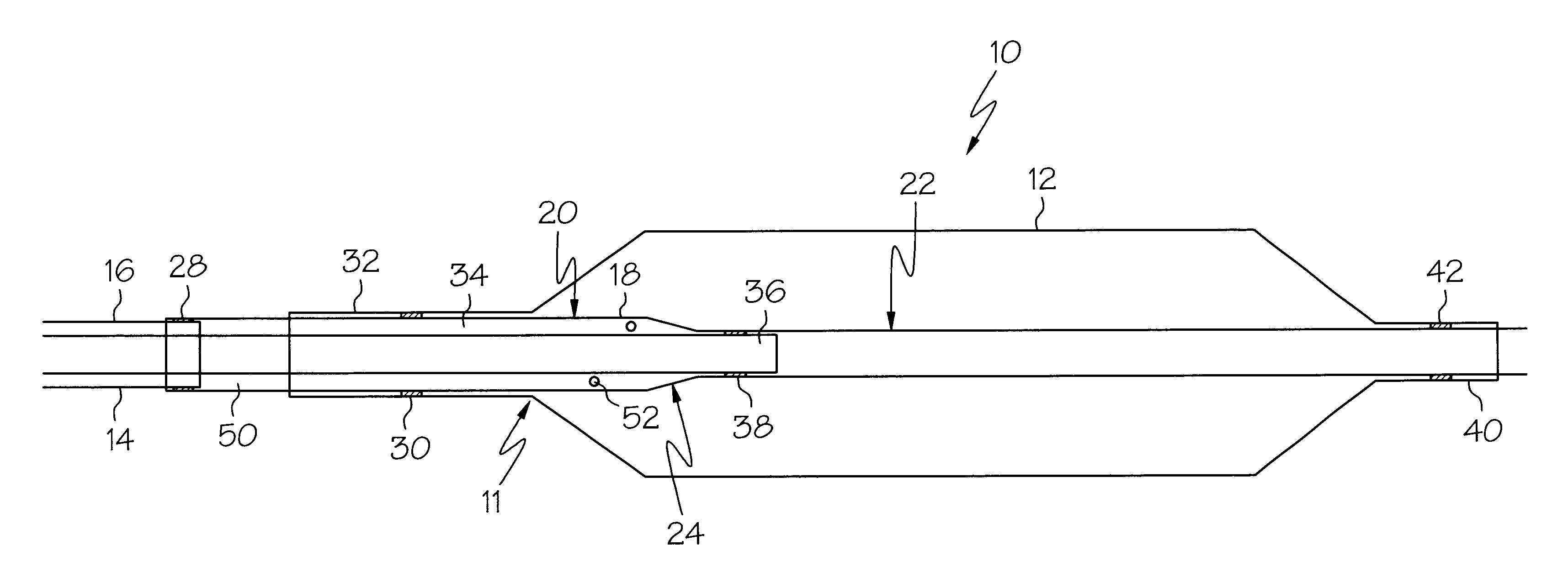
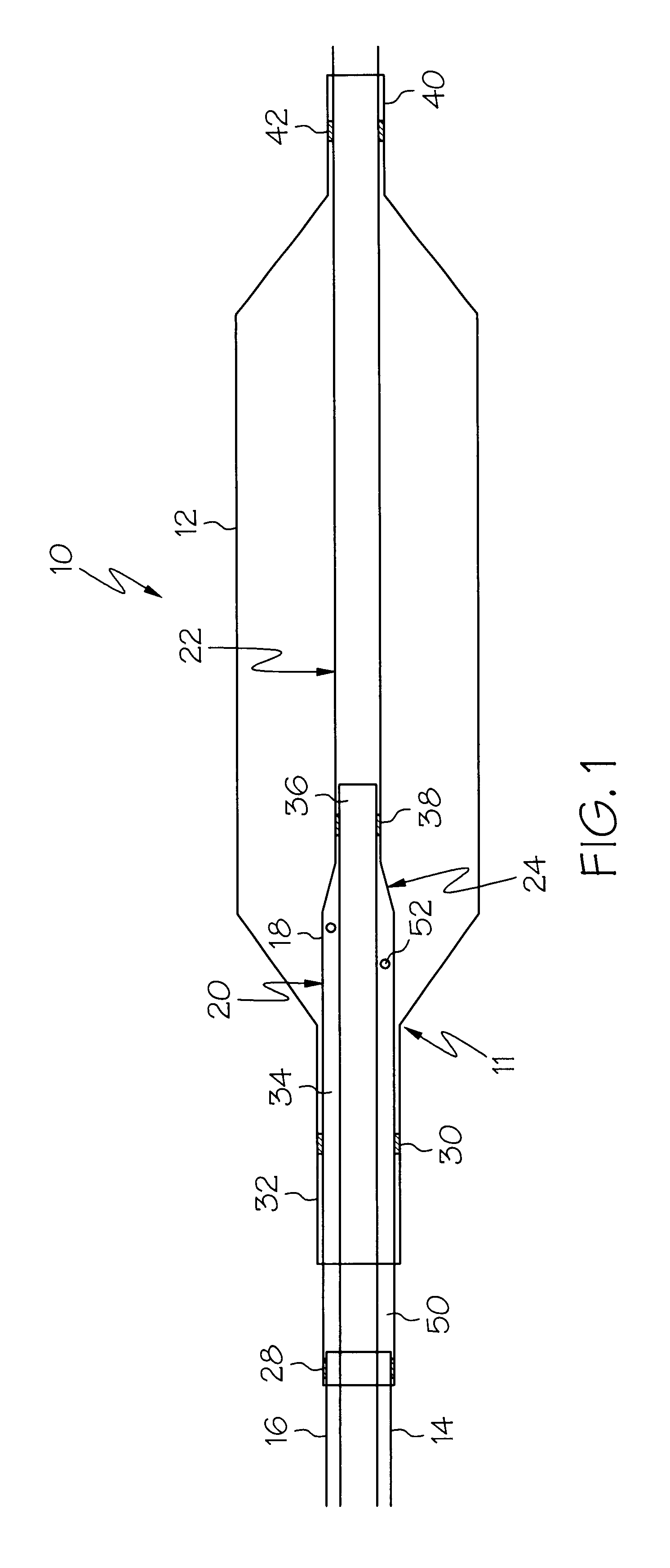
[0030]As previously discussed above, the present invention is directed to a variety of embodiments. For example, embodiments of the invention are depicted in FIG. 1, wherein a catheter, indicated generally at 10, is shown. The distal region 11 of catheter 10, is equipped with a balloon 12 that is expandable from a first expanded state to one or more expanded states. In FIG. 1 the balloon 12 is shown in an expanded state, such as the balloon would be placed in for dilatation of a vessel or delivery of a medical device such as a stent.

[0031]Catheter 10 comprises an inner shaft 14 as well as an outer shaft 16 disposed thereabout. In addition to shafts 14 and 16, the embodiment o...


PUM


Abstract

A balloon catheter comprises a balloon, an inner shaft, an outer shaft and a transition shaft. The transition shaft has a proximal portion and a distal portion joined by a tapered portion. The proximal portion has a diameter greater than the distal portion. The proximal portion has a first end portion engaged to at least a portion of the outer shaft at a first engagement site. At least a portion of the proximal waist is engaged to the proximal portion of the transition shaft at a second engagement site. At least a portion of the end region of the inner shaft is engaged to the distal portion of the transition shaft at a third engagement site. The distal portion extends through the balloon wherein at least a portion of the distal waist of the balloon is engaged to the distal portion of the transition shaft at a forth engagement site.

Description

CROSS-REFERENCE TO RELATED APPLICATIONS[0001]Not ApplicableSTATEMENT REGARDING FEDERALLY SPONSORED RESEARCH[0002]Not ApplicableBACKGROUND OF THE INVENTION[0003]1. Field of the Invention[0004]Embodiments of this invention are directed to the field of intravascular medical devices, and more particularly to the field of catheters such as angioplasty, neurological and guide catheters, among others, which may be used in various medical procedures such as percutaneous transluminal angioplasty (PTA), percutaneous transluminal coronary angioplasty (PTCA) as well as in procedures involving the placement of medicines and medical devices within the body.[0005]Some embodiments of the invention are directed to all forms of catheters which may be advanced through a body lumen or vessel. Some examples of catheters are over-the-wire (OTW) catheters, such as are described in U.S. Pat. No. 5,047,045; single-operator-exchange (SOE) balloon catheters, such as are described in U.S. Pat. Nos. 5,156,594 a...

Claims


Application Information

Patent Timeline
Patent Type & Authority Patents(United States)
IPC IPC(8): A61M25/00A61M29/02
CPCA61M25/0054A61M25/104A61M25/0043A61M25/0069A61M2025/1063
Inventor HOLMAN, THOMAS J.DUNN, RICHARDSEPPALA, JAN
Owner BOSTON SCI SCIMED INC
Why Eureka
Try Eureka