Vehicular turn-indicator system

a technology of turn indicator and turn indicator, which is applied in the direction of contact operating parts, contact mechanisms, transportation and packaging, etc., to achieve the effect of simple construction and facilitation of further stopping of the operation lever

Active Publication Date: 2005-10-11
KK TOKAI RIKA DENKI SEISAKUSHO
View PDF5 Cites 5 Cited by
  • Summary
  • Abstract
  • Description
  • Claims
  • Application Information

AI Technical Summary

Benefits of technology

[0008]The invention was made to solve the problem and an object thereof is to provide a vehicular turn-indicator system which can facilitate further the stopping of the operation lever and the bracket at the neutral position when they are returned from the left-turn indicating position or the right-turn indicating position to the neutral position with a simple construction.
[0022]According to the construction described above, when the cancel cam is rotated to the opposite side to the direction indicated by the operation lever and the bracket, which are positioned at the left-turn indicating position or the right-turn indicating position, the ratchet is rotated by the cancel cam, whereby the bracket and hence the operation lever are returned to the neutral position. As this occurs, while the ratchet is rotating about the shaft portion, the shaft portion moves relatively along the cam projecting portion. Then, the shaft portion is restricted from passing across the apex portion of the cam projecting portion to the opposite side by the restricting projecting portion provided in the vicinity of the apex portion of the cam projecting portion, and as a result, it is ensured that the bracket stops at the neutral position. In this case, since the restricting projecting portion may be formed into any shape which can restrict the passage of the shaft portion across the apex portion of the cam projecting portion to the opposite side, the setting of the construction for restricting the passage of the shaft portion across the neutral position becomes easier when compared with the related example in which the projecting portion is provided to which the excess movement restricting piece is brought into abutment, and hence the construction of the system can be made simple.
[0023]According to the aspect of the invention, when returning the operation lever and the bracket, which are positioned at the left-turn indicating position or the right-turn indicating position, to the neutral position, the stopping of the operation lever and the bracket at the neutral position can be facilitated further.

Problems solved by technology

In the vehicular turn-indicator system disclosed in the patent document 1, however, there exists a problem that imparting a proper gradient to the sloping surfaces of the projecting portion with which the excess movement restricting pieces is brought into abutment.

Method used


Image

  • Vehicular turn-indicator system
  • Vehicular turn-indicator system
  • Vehicular turn-indicator system

Examples


Embodiment Construction

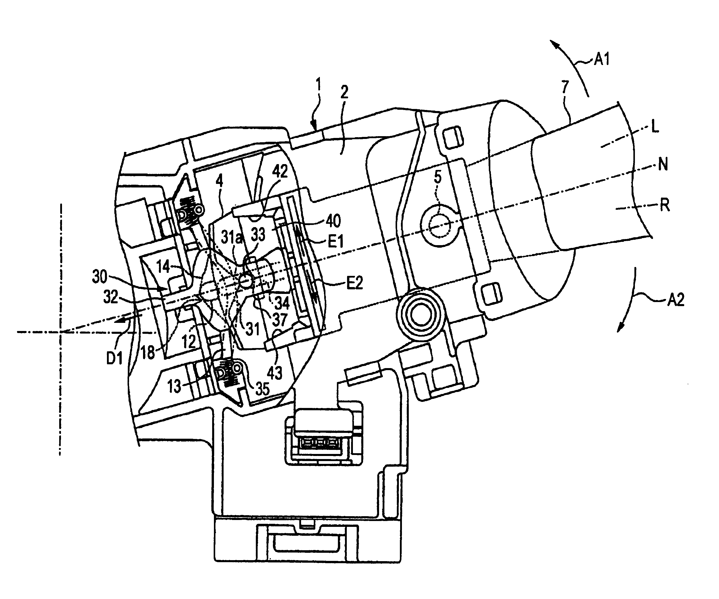
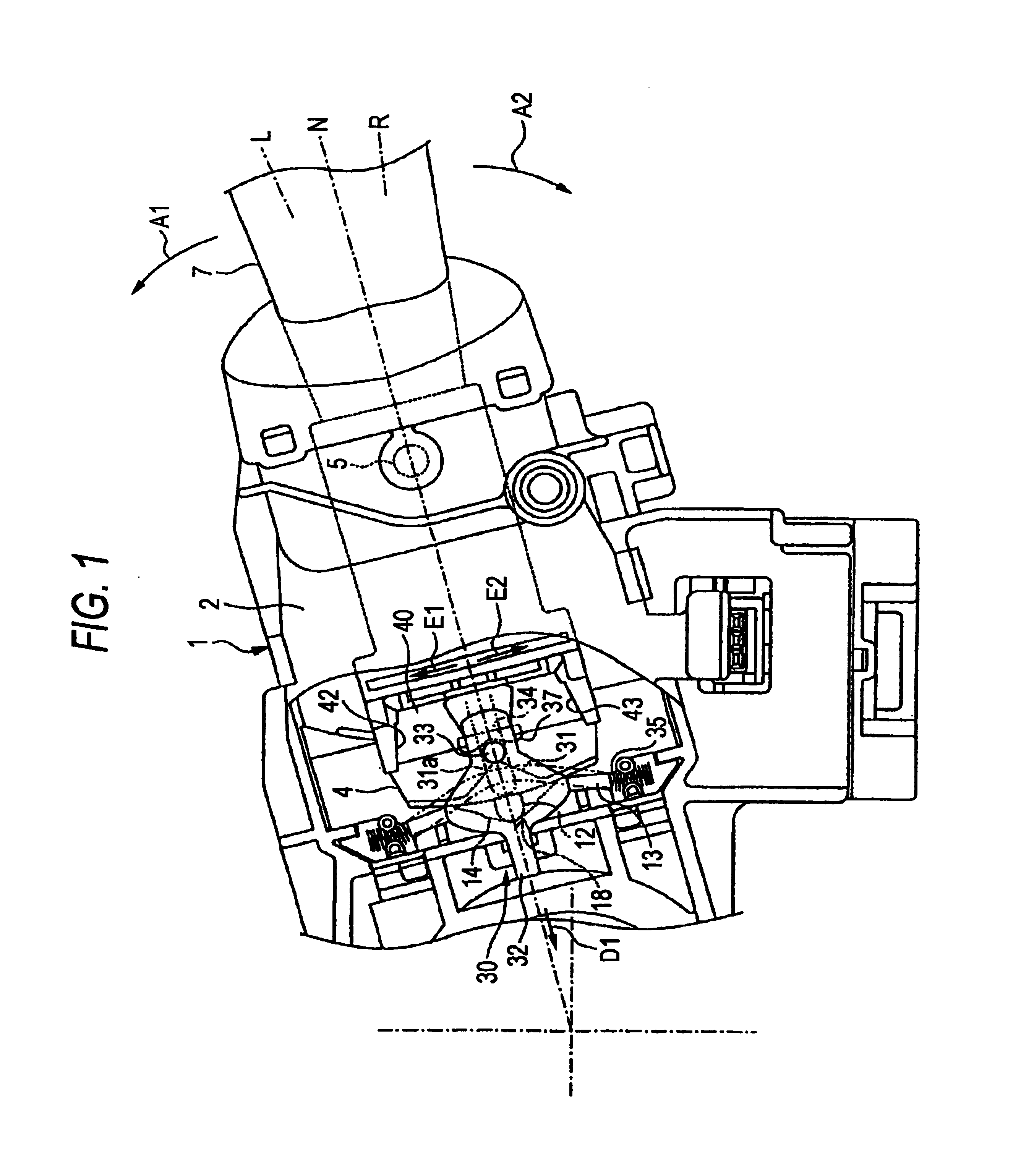
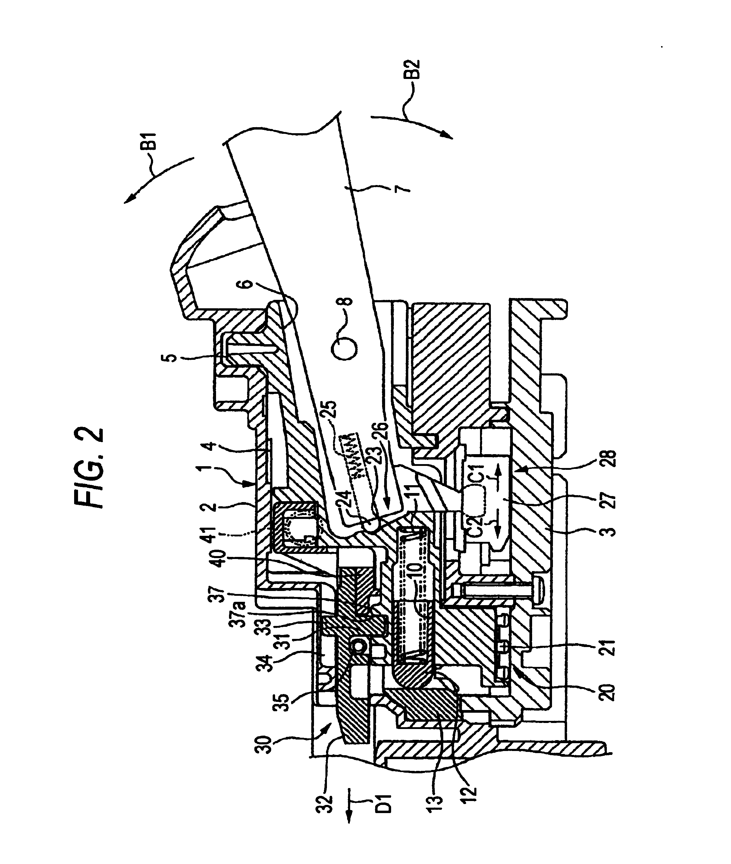
[0029]Hereinafter, an embodiment of the invention will be described by reference to the accompanying drawings. Firstly, in FIGS. 1 and 2, a unit case 1 of a turn-indicator system is provided on a column cover portion through which a steering shaft, not shown, is passed in such a manner as to project sideways from the column cover portion. This unit case 1 is made up of a combination of an upper cover 2 and a lower wiring circuit board 3, and a bracket 4 is provided in the unit case 1 in such a manner as to rotate about a shaft 5 in a direction indicated by an arrow A1 and a direction indicated by an arrow A2 in FIG. 1. A lever inserting portion 6 is formed in the bracket 4, and a proximal end portion of an operation lever 7 is inserted into this lever inserting portion 6. The operation lever 7 is provided in such a manner as to rotate relative to the bracket 4 about a shaft 8 in a direction indicated by an arrow B1 and a direction indicated by an arrow B2 in FIG. 2, as well as in su...


PUM


Abstract

A restricting projecting portion is provided on an upper surface of a bracket in the vicinity of an apex portion of an angled cam projecting portion for guiding the movement of a shaft portion of a ratchet. When an operation lever and a bracket are returned to a neutral position from a left-turn indicating position or a right-turn indicating position, the force of the shaft portion of the ratchet is weakened through the abutment of the shaft portion of the ratchet against a bearing surface of the restricting projecting portion, whereby the passage of the shaft portion across the apex portion of the cam projecting portion to an opposite side is restricted. This facilitates the stopping of the bracket and hence the operation lever at the neutral position.

Description

BACKGROUND OF THE INVENTION[0001]The present invention relates to a vehicular turn-indicator system which facilitates the stopping of an operation lever and a bracket at a neutral position when the operation lever and the bracket are returned to the neutral position from a left- or right-turn indicating position.[0002]A related vehicular turn-indicator system is constructed as below. A turn direction indicating operation lever is designed to be operated to rotate together with a bracket about a neutral position between a left-turn indicating position and a right-turn indicating position relative to a case. An excess movement restricting surface of an excess movement restricting mechanism is provided on the case side. The excess movement restricting surface has a neutral position root portion which is positioned between two sloping surfaces and a left-turn indicating position holding portion and a right-turn indicating position holding portion which are positioned on sides of the neu...

Claims


Application Information

Patent Timeline
Patent Type & Authority Patents(United States)
IPC IPC(8): B60Q1/34B60Q1/42B60Q1/40
CPCB60Q1/425
Inventor NAITO, HIROYUKI
Owner KK TOKAI RIKA DENKI SEISAKUSHO
Why Eureka
Try Eureka