
Perpendicular magnetic recording head with nonmagnetic write gap greater than twice side shield gap distance

a magnetic recording head and perpendicular magnetic technology, applied in the field of magnetic read and write heads, can solve the problems of ineffective use of high-density recording, inability to control the width of recorded tracks, and probability of adjacent track erasure, so as to improve writer efficiency, suppress side writing, and high write field gradient

Inactive Publication Date: 2005-10-11
SEAGATE TECH LLC
View PDF6 Cites 245 Cited by
  • Summary
  • Abstract
  • Description
  • Claims
  • Application Information

AI Technical Summary

Benefits of technology

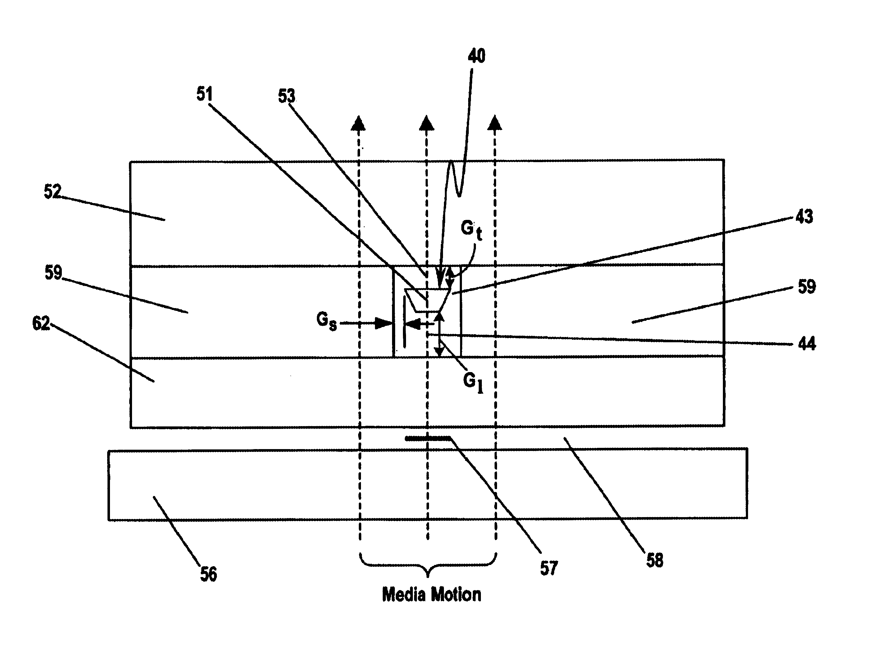
[0007]The present invention provides a magnetic read / write head design for high-track density recording on double layer perpendicular media with suppressed side writing. The magnetic read / write head of the present invention includes a main pole, a first return pole and magnetic side shields magnetically connected to the first return pole to suppress side writing. The main pole is separated from the first return pole by the write gap in down-track direction and from the magnetic side shield by narrow nonmagnetic gaps in the cross-track direction. To improve the writer efficiency and provide high write field gradient, the length of the write gap should be more than twice the distance between the ABS and the soft magnetic underlayer. Side writing at skew angles is suppressed by providing for the trailing edge of the main pole to be larger than the leading edge of the main pole at the ABS. A side connecting the leading and trailing edge should create an angle that is not less than the maximal skew angles in the drive.
[0008]In an alternative embodiment, the magnetic read / write head includes a main pole, a first return pole, a second return pole and magnetic side shields magnetically connected to the first and second return poles to suppress side writing. The main pole is separated from the first return pole by the leading write gap in up-track direction. The main pole is also separated from the second return pole by the trailing write gap in down-track direction and the side magnetic shield by narrow nonmagnetic side gaps in the cross-track direction. The leading gap is at least twice the distance of the trailing gap in order to improve writer efficiency and provide high gradient of the write field.

Problems solved by technology

The write head of the '151 patent can not control the width of the recorded tracks and hence cannot be used effectively for high track density recording.
Due to the shallow field decay profile in cross-track direction, the recorded tracks of the device described in the '151 patent are relatively wide and there is a probability of adjacent track erasure.
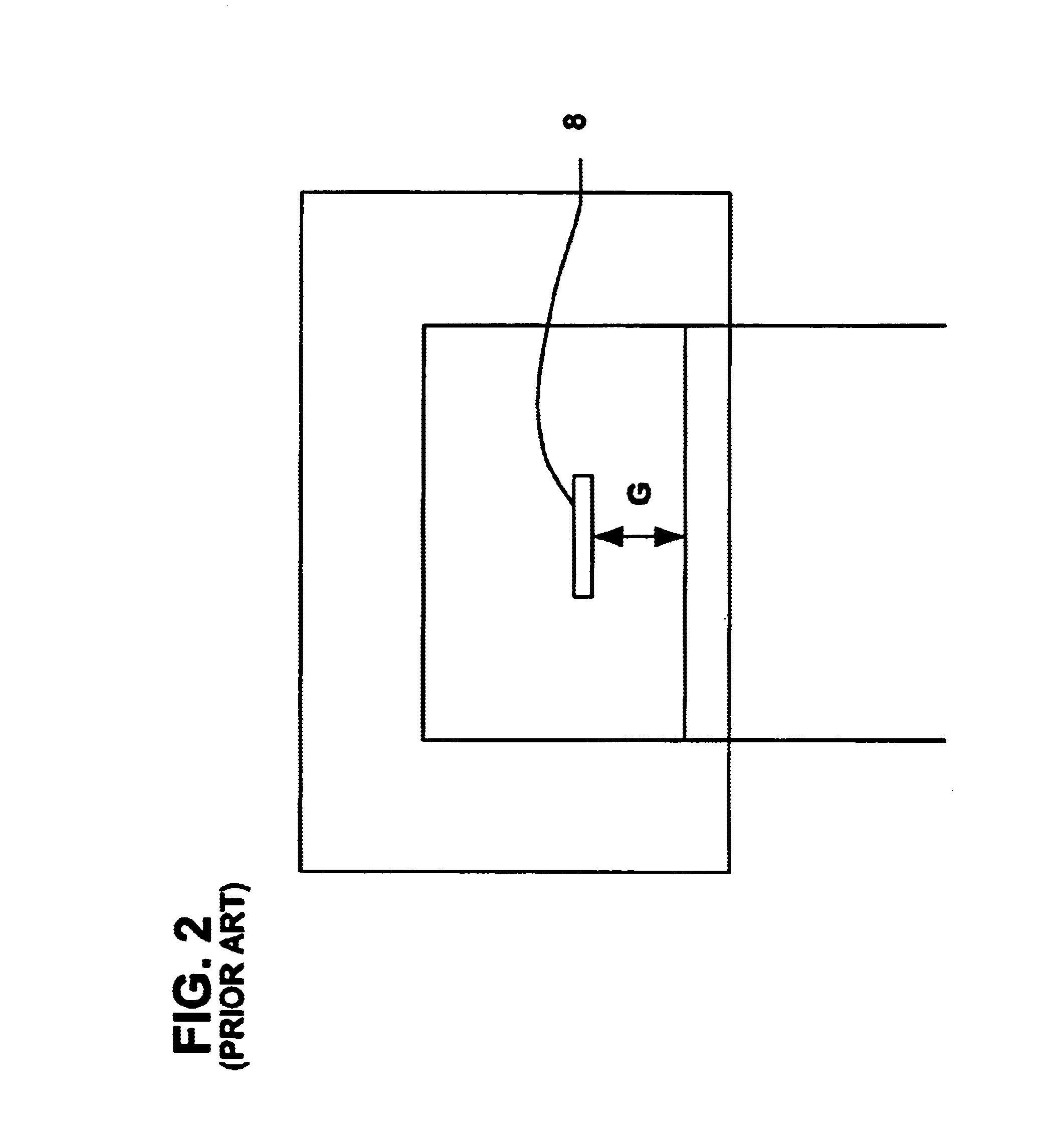
As described in the '546 patent, the distance of write gap G is in the range from D / 2 to 2D and the distance of side gaps Gs can be larger than the distance G. The distances of write gap and side gaps that is described in the '546 patent substantially reduce efficiency of the writer and do not support high-track density recording on high coercivity media.
That limits the application of '546 high areal density recording due to necessity of higher media coercivity exhibiting high thermal stability.

Method used


Image

  • Perpendicular magnetic recording head with nonmagnetic write gap greater than twice side shield gap distance
  • Perpendicular magnetic recording head with nonmagnetic write gap greater than twice side shield gap distance
  • Perpendicular magnetic recording head with nonmagnetic write gap greater than twice side shield gap distance

Examples


Embodiment Construction

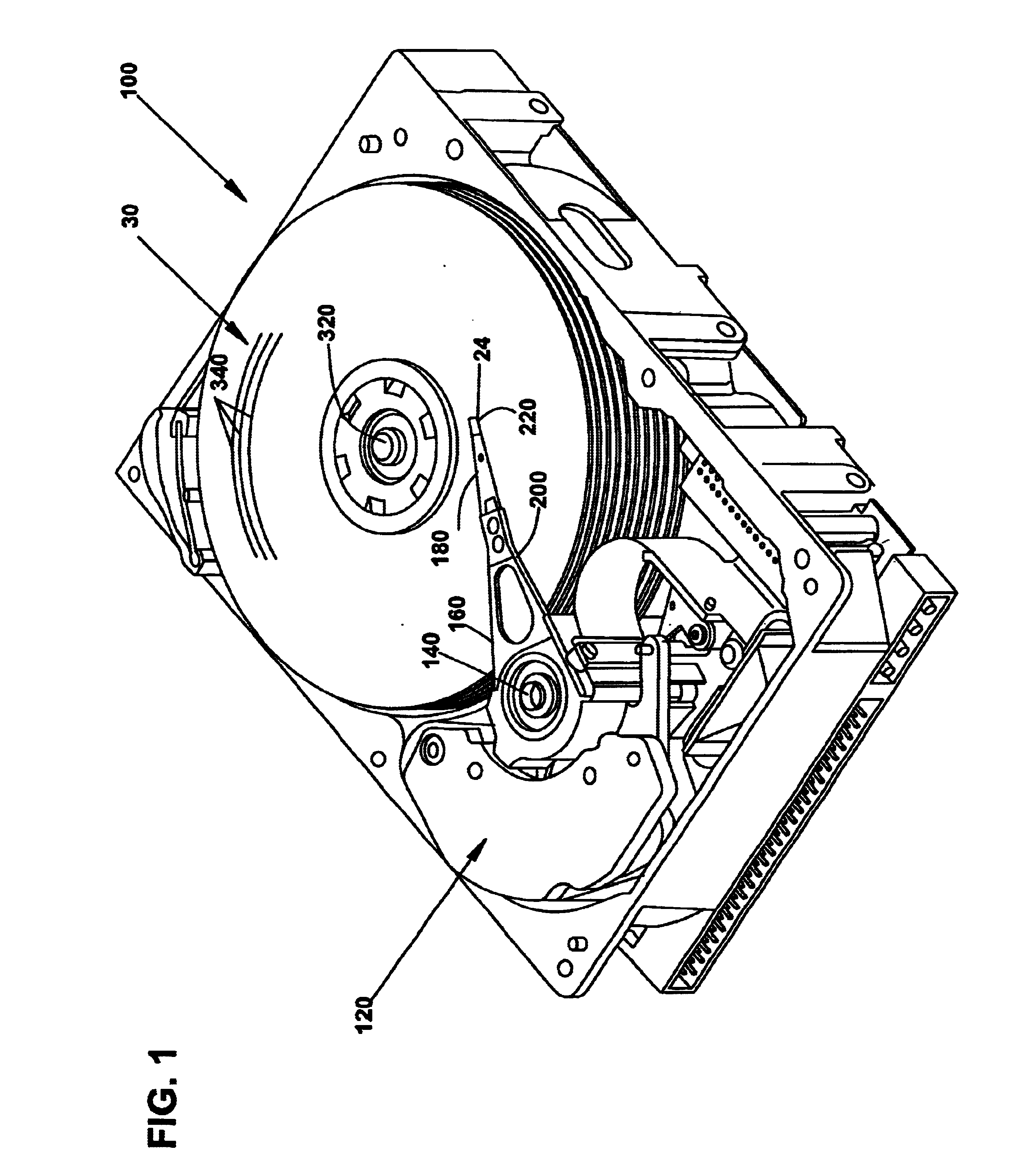
[0025]FIG. 1 is a perspective view of a disc drive 100 including a dual-stage disc drive actuation system for positioning a head-carrying slider over a track 340 of disc 30. Disc drive 100 includes voice coil motor 120 arranged to rotate actuator arm 160 on a spindle around axis 140. Head suspension 180 is connected to actuator arm 160 at head mounting block 200. A microactuator is attached to head suspension 180 by flexure 220 and carries slider 24, which in turn carries a transducing head for reading and / or writing data on concentric tracks on disc 30. Disc 30 rotates around axis 320, so that windage is encountered by slider 24 to keep it aloft a small distance above the surface of disc 30.

[0026]FIGS. 2 and 3 illustrate a conventional head for perpendicular recording that has been described in U.S. Pat. No. 5,181,151 ('151), issued to Masami Yamashita et al. Magnetization transitions on the double layer perpendicular media 300 are recorded by the trailing top edge of trailing main...


PUM

PropertyMeasurementUnit
distanceaaaaaaaaaa
distanceaaaaaaaaaa
distanceaaaaaaaaaa

Abstract

A magnetic head for perpendicular recording on double layer media with suppressed side writing and controlled write width is disclosed. The present invention reduces the problem of side writing and controls the write width of the writing element by providing a writing element with a trailing edge sized dimensionally larger than the leading edge, side shields, and specifically spaced writing gaps placed at various distances between the write element and the side shields, return poles, and the main pole.

Description

CROSS REFERENCE TO RELATED APPLICATIONS[0001]This application claims the benefit of U.S. Provisional Application No. 60 / 293,278, filed May 23, 2001.FIELD OF THE INVENTION[0002]The present invention generally relates to magnetic read and write heads for high areal density recording on double layer perpendicular media, and in particular the present invention relates to the writing portion of such head wherein such head has control over the width of the recorded track and skew effect.BACKGROUND OF THE INVENTION[0003]As the density of data tracks on magnetic discs continues to increase, increased efficiency of the magnetic read / write head is required. Perpendicular recording, as opposed to the more conventional longitudinal recording, is a form of magnetic recording in which magnetic moments representing bits of data are orientated perpendicularly to the surface of the recording layer of the recording medium. Perpendicular recording may offer advantages over longitudinal recording, such...

Claims


Application Information

Patent Timeline
Patent Type & Authority Patents(United States)
IPC IPC(8): G11B5/127G11B5/187G11B5/31G11B5/11
CPCG11B5/11G11B5/1278G11B5/3116G11B5/3146G11B5/315G11B5/1871G11B5/312
Inventor SHUKH, ALEXANDER M.TABAT, NED
Owner SEAGATE TECH LLC
Learn More