Bandwidth control system

a control system and bandwidth technology, applied in the field of network bandwidth control system, can solve the problems of inefficient packet scheduling, increased need for qos technology, and disadvantageous predictive nature of algorithms such as cbq

Inactive Publication Date: 2005-10-11
DYBAND CORP
View PDF57 Cites 78 Cited by
  • Summary
  • Abstract
  • Description
  • Claims
  • Application Information

AI Technical Summary

Benefits of technology

[0008]Briefly stated, the present invention provides a bandwidth control system for a network, the network having a host computer that includes a first network interface and a second network interface. The bandwidth control system comprising a packet driver and a traffic shaper. The packet driver is adapted to be executed on the host computer and is logically connected to the first network interface and the second network interface. The packet driver captures packets received from the network on the first network interface. The traffic shaper is adapted to be executed on the host computer and maintains a topology representation of the network, the topology representation including one or more nodes. The traffic shaper performs priority and packet rate metering functions on the captured packets to match a set of rate conditions unique...

Problems solved by technology

Moreover, the need for QoS technology will only continue to increase as the growth of network traffic, both through the public Internet and private LANs and WANs, continues at a rapid pace.
Algorithms such as CBQ, however, are disadvantageous in that they are predictive in nature.
Such estimates are inaccurate due to the burstiness and unpredictability of network traffic, leading to inefficient packet scheduling and the possibility of network congestion.
Algorithms such as CBQ are also disadvantageous in needing to keep fairly accurate information regar...

Method used


Image

  • Bandwidth control system
  • Bandwidth control system
  • Bandwidth control system

Examples


Embodiment Construction

[0038]Certain terminology is used herein for convenience only and is not to be taken as a limitation on the present invention.

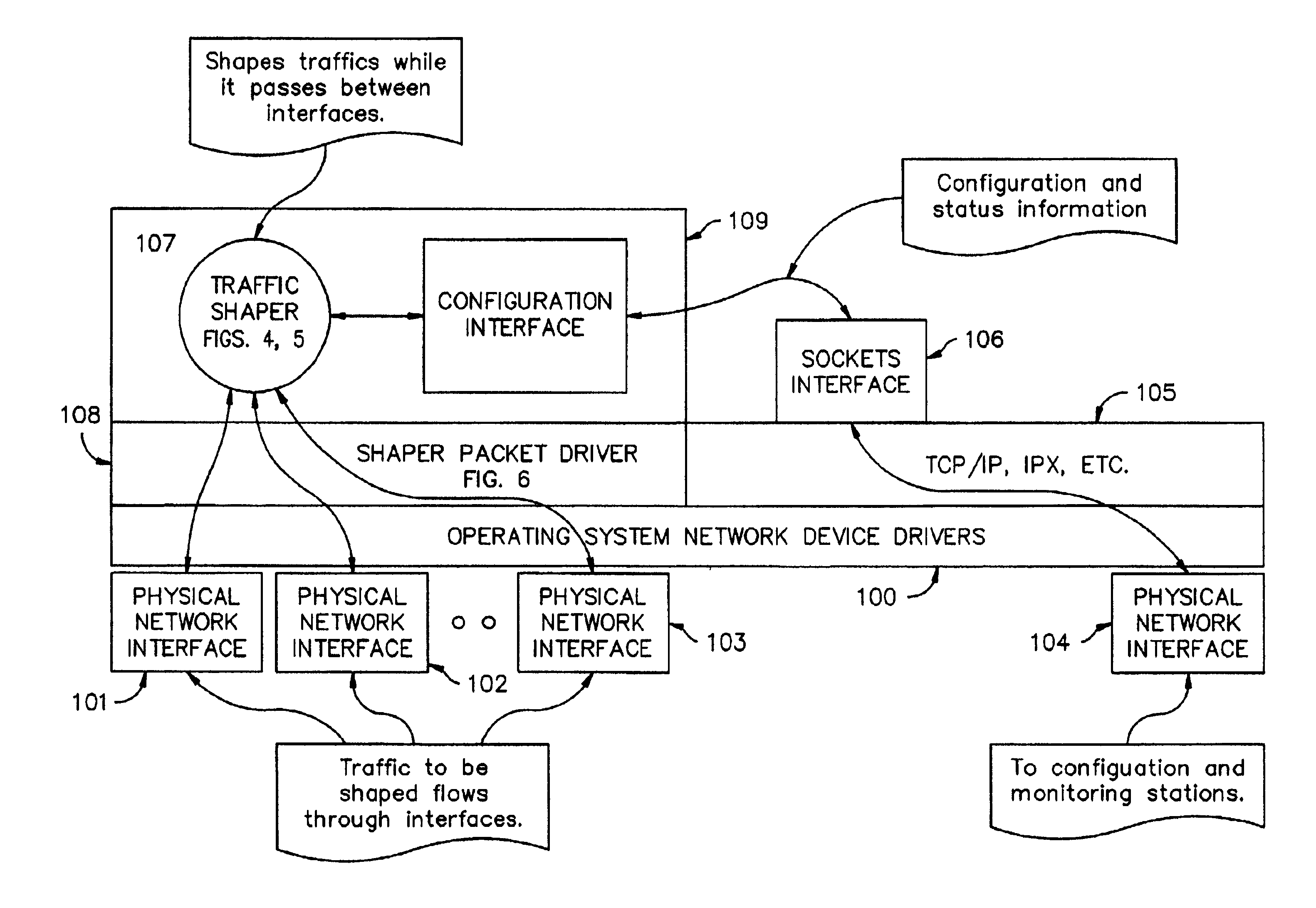
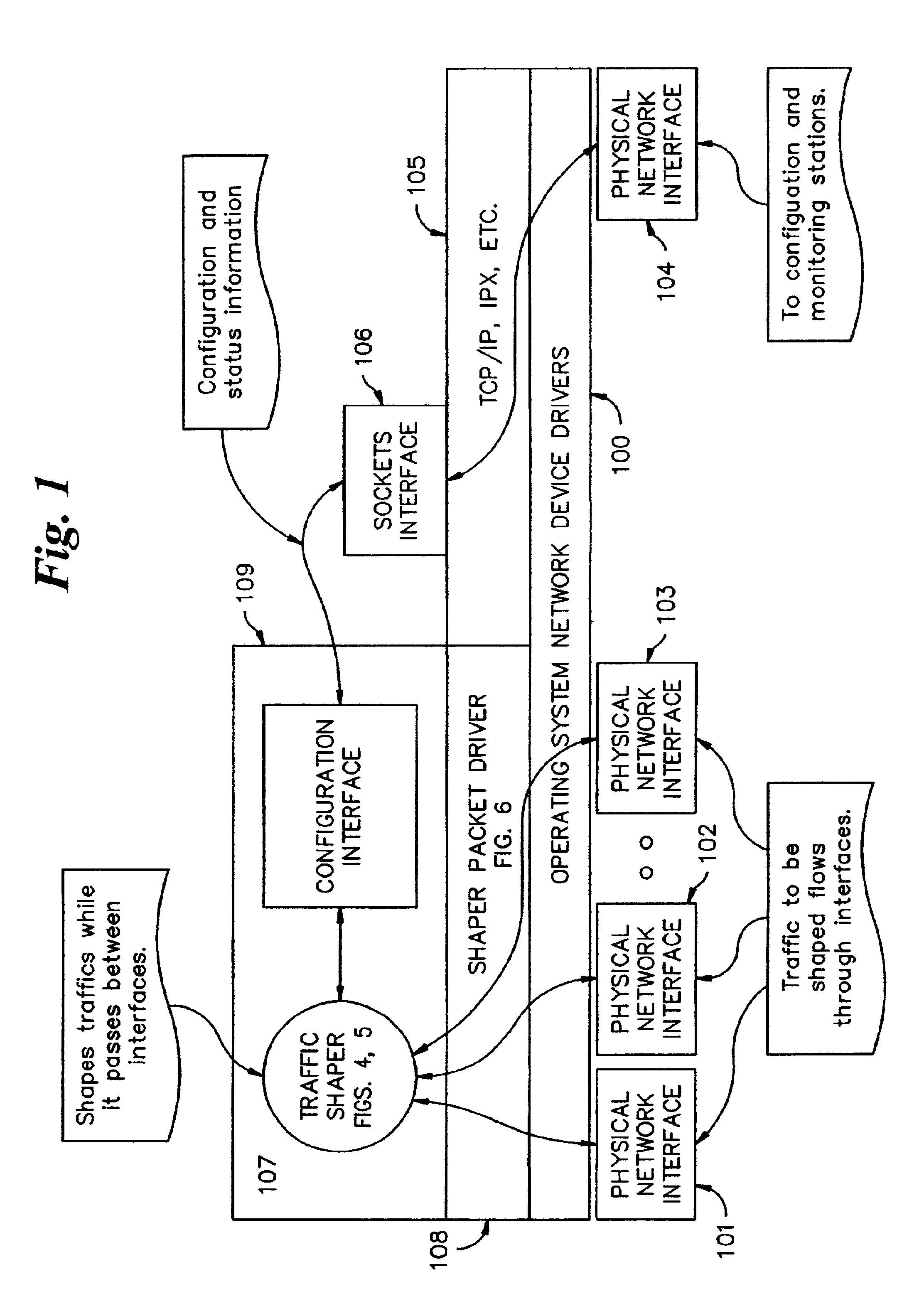
[0039]Referring to FIG. 1, a preferred embodiment of the bandwidth control system includes a host operating system and network device drivers 100 connecting to physical network adapters 101, 102, 103, 104, a network protocol stack 105 and Unix style sockets layer 106, all of which are generally provided within a host operating system such as Unix, Linux, Sun Solaris, or Microsoft NT.

[0040]The preferred embodiment of the present invention adds a traffic shaper 107, a packet driver 108, and a configuration interface 109 to the host operating system resources 100 through 106 described above.

[0041]In the preferred embodiment described, the TCP / IP network protocol and an Ethernet physical medium were chosen as an example, although other network protocols and physical network types may be easily implemented by one skilled in the art without departing from the spiri...


PUM


Abstract

A bandwidth control system for a network, the network having a host computer that includes a first network interface and a second network interface. A packet driver adapted to be executed on the host computer is logically connected to the first network interface and the second network interface. The packet driver captures packets received from the network on the first network interface. A traffic shaper adapted to be executed on the host computer maintains a topology representation of the network, the topology representation including one or more nodes. The traffic shaper performs priority and packet rate metering functions on the captured packets to match a set of rate conditions unique to each node in the topology representation of the network. The captured packets are returned to the packet driver for transmission to the network on the second network interface.

Description

CROSS REFERENCE TO RELATED APPLICATIONS[0001]The present application is based on and claims the benefit of U.S. Provisional Application No. 60 / 195,000, filed Apr. 5, 2000, entitled “BANDWIDTH CONTROL SYSTEM,” which is herein incorporated by reference in its entirety.COPYRIGHT NOTICE AND AUTHORIZATION[0002]Portions of the documentation in this patent document contain material that is subject to copyright protection. The copyright owner has no objection to the facsimile reproduction by anyone of the patent document or the patent disclosure as it appears in the Patent and Trademark Office file or records, but otherwise reserves all copyright rights whatsoever.BACKGROUND OF THE INVENTION[0003]The present invention relates generally to a bandwidth control system for networks, and more particularly to a system in which network traffic that flows through the system is prioritized and shaped to match a set of rate conditions unique to each of a hierarchy of arbitrary physical and logical ag...

Claims


Application Information

Patent Timeline
IPC IPC(8): H04L12/56H04L12/24H04J3/16
CPCH04J3/1682H04L41/0896H04L41/12H04L47/10H04L47/22H04L47/24
Inventor HORTON, JAMESHOLLOPETER, LOISNUNES, VICTORSEARCY, SCOTTTHOMAS, DAVID
Owner DYBAND CORP
Why Eureka
Try Eureka