Device for forming a leno selvedge

a technology of leno selvedge and forming device, which is applied in the field of leno selvedge devices, can solve the problems of affecting the quality the inability of the lifting heald to take hold, and the damage to the loom is considerable, so as to achieve the effect of reducing the damage resulting from half healds falling out of the leno selvedge device and less load

Active Publication Date: 2005-10-18
GEBR KLOCKER
View PDF9 Cites 14 Cited by
  • Summary
  • Abstract
  • Description
  • Claims
  • Application Information

AI Technical Summary

Benefits of technology

[0004]In accordance with the invention, the solution to this object is achieved in that each lifting heald has at least one magnet in the region of its upper end, the magnets of the two lifting healds of a leno selvedge device being polarized such that the healds attract each other. If it is made certain that the two lifting healds of a leno selvedge device are adjacent at their end sides in the region of their upper end, there is little risk that they be positioned in the above mentioned “X” shape in the region of their lower end. More specifically if the magnets in the lower portion of the lifting healds, meaning in the transition zone between the lower leg and the securing element, are polarized such that the lifting healds of a leno selvedge device again attract each other, there is no risk that the lifting healds be oriented in such an “X” shape in the way mentioned herein above. This means that, even if the number of wefts is high, the legs of the lifting healds of a leno selvedge device are always parallel, thus preventing the half heald from ascending even if the thread has broken while this parallel orientation of the lifting healds also results in far less load on the half heald.
[0005]It has further been found that damages resulting from half healds having fallen out of the leno selvedge device could be substantially reduced.
[0009]In arranging the magnets as described herein above, more specifically as far as their polarization is concerned, one achieves that two neighboring leno selvedge devices having two lifting healds repulse each other. This means that, depending on the magnetic force of the magnets, two neighboring lifting healds are always spaced apart, this spacing preventing the lifting healds of one leno selvedge device from rubbing against the lifting healds of a neighboring leno selvedge device. Such a friction, and the wear it implies, are thus largely avoided.

Problems solved by technology

This results in a knock-kneed position of the two lifting healds of a leno selvedge device relative to each other.
This signifies that, more specifically upon rupture of the stationary thread, there is a risk that, within a very short period of time on fast looms i.e., on looms with a very high number of wefts, the half heald is no longer held by the magnets but ascends so that in the end the lifting heald is no longer capable of taking hold thereof and the half heald falls into the loom.
If the loom cannot be stopped immediately because e.g., the rupture of the thread has not been noticed immediately, this may cause considerable damage to the loom.

Method used


Image

  • Device for forming a leno selvedge
  • Device for forming a leno selvedge
  • Device for forming a leno selvedge

Examples


Embodiment Construction

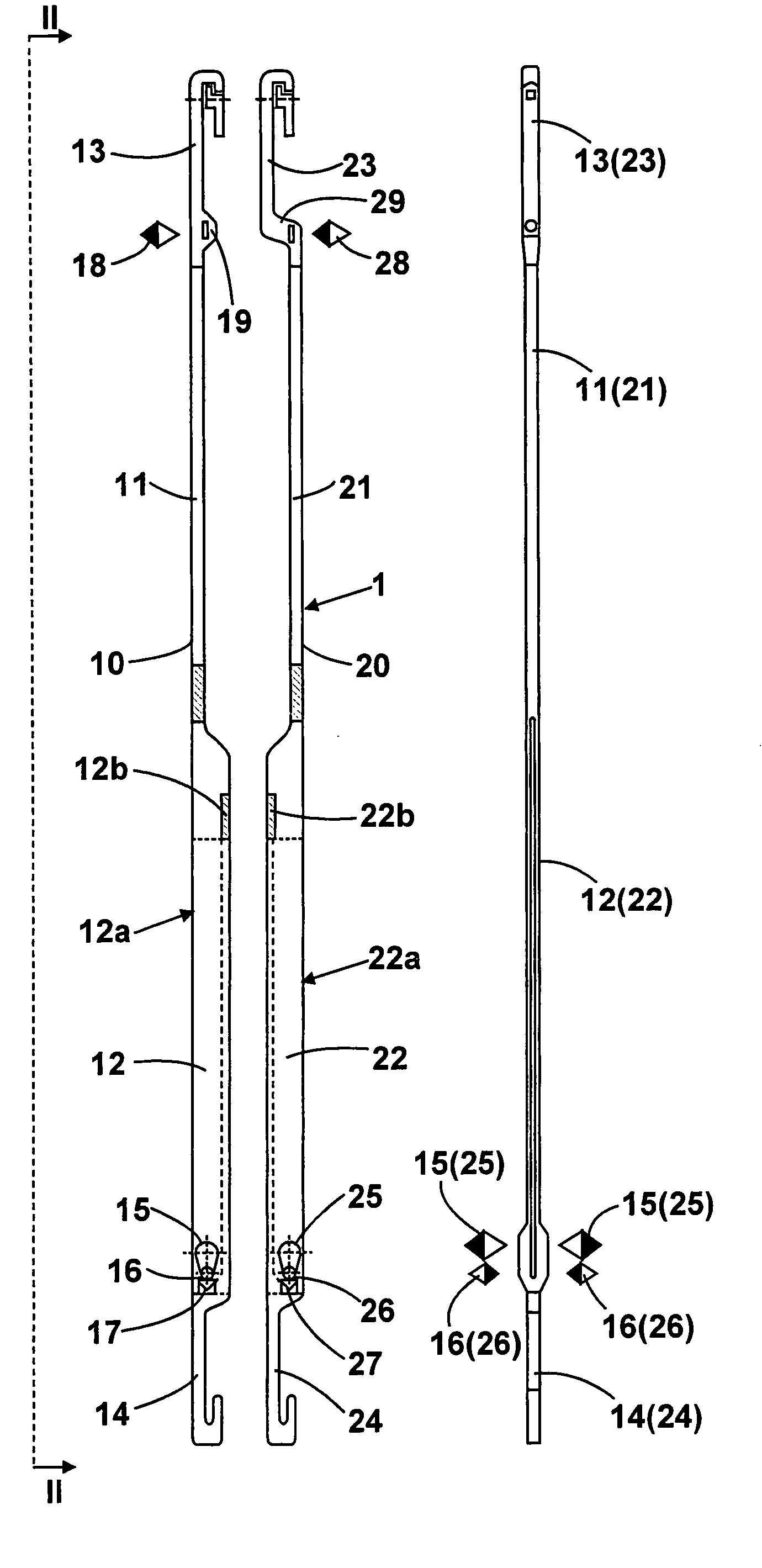
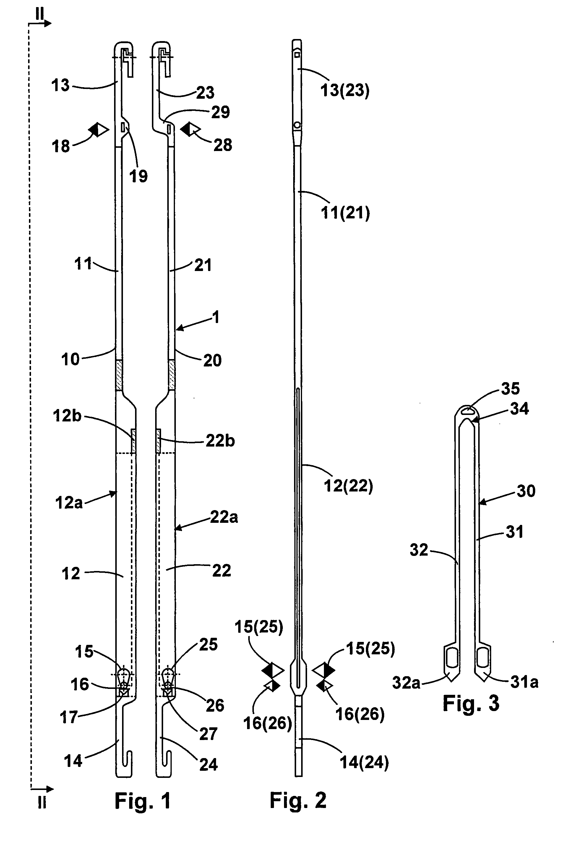
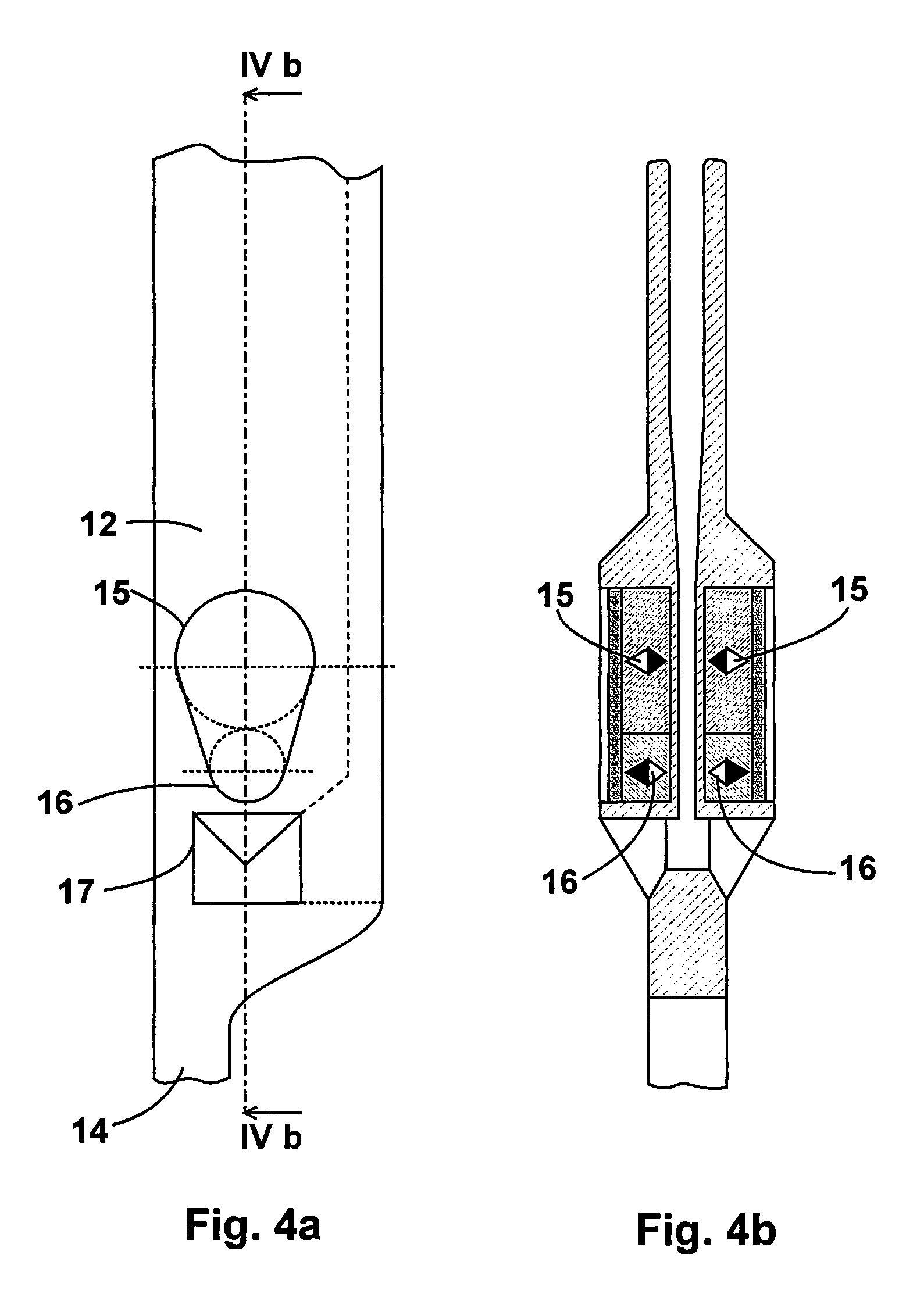
[0020]The leno selvedge device 1 comprises the two lifting healds 10 and 20 and the half heald 30. Each lifting heald 10, 20 has an upper leg 11, 21 and a lower leg 12, 22, each leg being adjoined with a securing element 13, 23 and 14, 24 respectively by means of which the lifting healds are secured to the heald ridge bars of the loom. The lifting healds 10, 20 receives the half heald indicated at 30. The fabrication principle of a leno selvedge using a leno selvedge device comprised of lifting healds and half healds is sufficiently well known. In this connection, the reader is referred to DE 38 18 680 C1 or to DE 297 038 96 U1, both describing the type of fabrication of a leno selvedge device. The half heald 30 has the two legs 31, 32 with the feet 31a, 32a provided at their end. Each lifting heald 10, 20 has a seat 12b and 22b respectively located in the region of the slot 12a and 22a respectively, the half heald resting thereon with its U-shaped end (arrow 34) in the region of th...


PUM


Abstract

A device (1) for forming a leno selvedge, said device having two lifting healds (10, 20) and one half heald (30), the lifting healds (10, 20) having a securing element (13, 23; 14, 24) provided respectively at the upper and lower end thereof, said lifting healds (10,20) having, in the region of the lower end, at least one magnet for the foot (31a, 32a) of the half heald (30), each lifting heald (10, 20) having at least one magnet (18, 28) in the region of its upper end, the magnets (18, 28) of the two lifting healds (10, 20) of a leno selvedge device being polarized such that the healds attract each other.

Description

FIELD OF THE INVENTION[0001]The present invention relates to a device for forming a leno selvedge, said device comprising two lifting healds and one half heald, the lifting healds having a securing element provided respectively at the upper and lower end thereof, said lifting healds having, in the region of the lower end, at least one magnet for the foot of the half heald.DESCRIPTION OF THE PRIOR ART[0002]A leno selvedge device of the type mentioned herein above is described in DE 297 03 896 U1 and consists, as already explained, of two lifting healds and of one half heald that is alternately taken along by one of the lifting healds. The lifting healds are for their part mounted on heald ridge bars of the heald frames or on the heald frames themselves. In principle, a half heald is characterized by a U-shaped configuration, with the two legs joining at their upper end to form an eye for guiding the stationary thread. At their lower end, the legs of the half heald have a half heald f...

Claims


Application Information

Patent Timeline
Patent Type & Authority Patents(United States)
IPC IPC(8): D03C7/00D03C7/02D03C7/06
CPCD03C7/02
Inventor HOCKEMEYER, KURTKLOCKER, MATTHIAS
Owner GEBR KLOCKER
Why Eureka
Try Eureka