Dispenser for paste-like products

a technology of paste-like products and dispensers, which is applied in the direction of volume meters, instruments, single-unit apparatuses, etc., can solve the problems of loss of pressure, impairment of paste-like products, and product delivery through non-return valves, so as to improve haptic properties

Inactive Publication Date: 2005-10-18
INOTECH KUNSTOFFTECHNIK GMBH
View PDF16 Cites 10 Cited by
  • Summary
  • Abstract
  • Description
  • Claims
  • Application Information

AI Technical Summary

Benefits of technology

[0026]It has been found that the material for the sealing member can be used particularly preferably for forming a functional surface on the outer surface of the headpiece at the front side. Such a functional surface may e.g. be a pusher surface which improves the haptic properties and against which the user of the dispenser ...

Problems solved by technology

The delivery of paste-like material through the non-return valve also leads to a loss in pressure, which is disadvantageous insofar as this requires the application of increased pressure forces for compensating said loss in pressure to axially displace the headpiece towards the container.
Moreover, there is the problem that the product delivered through the non-return valve is present in those delivery portions of the di...

Method used


Image

  • Dispenser for paste-like products
  • Dispenser for paste-like products
  • Dispenser for paste-like products

Examples


second embodiment

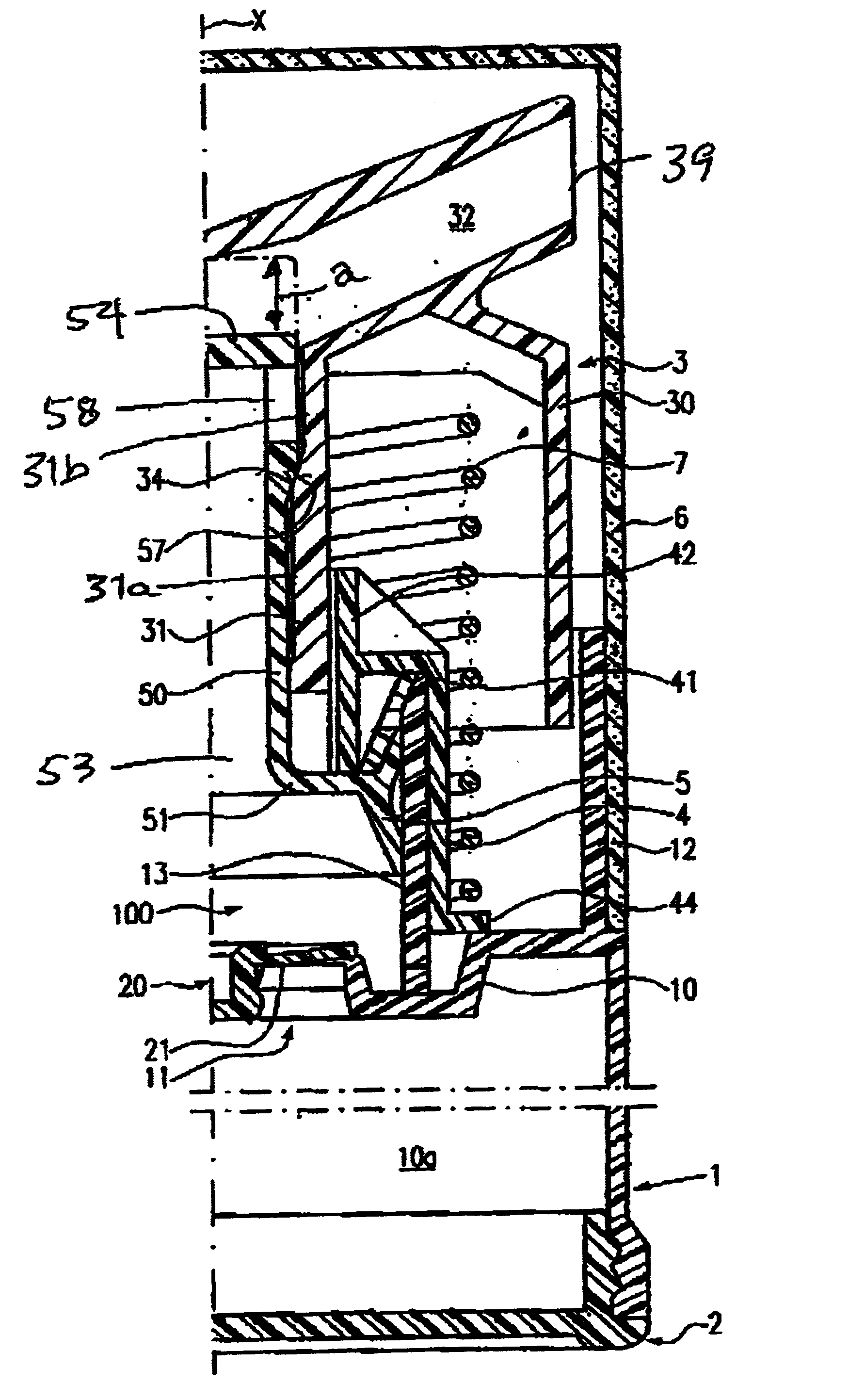
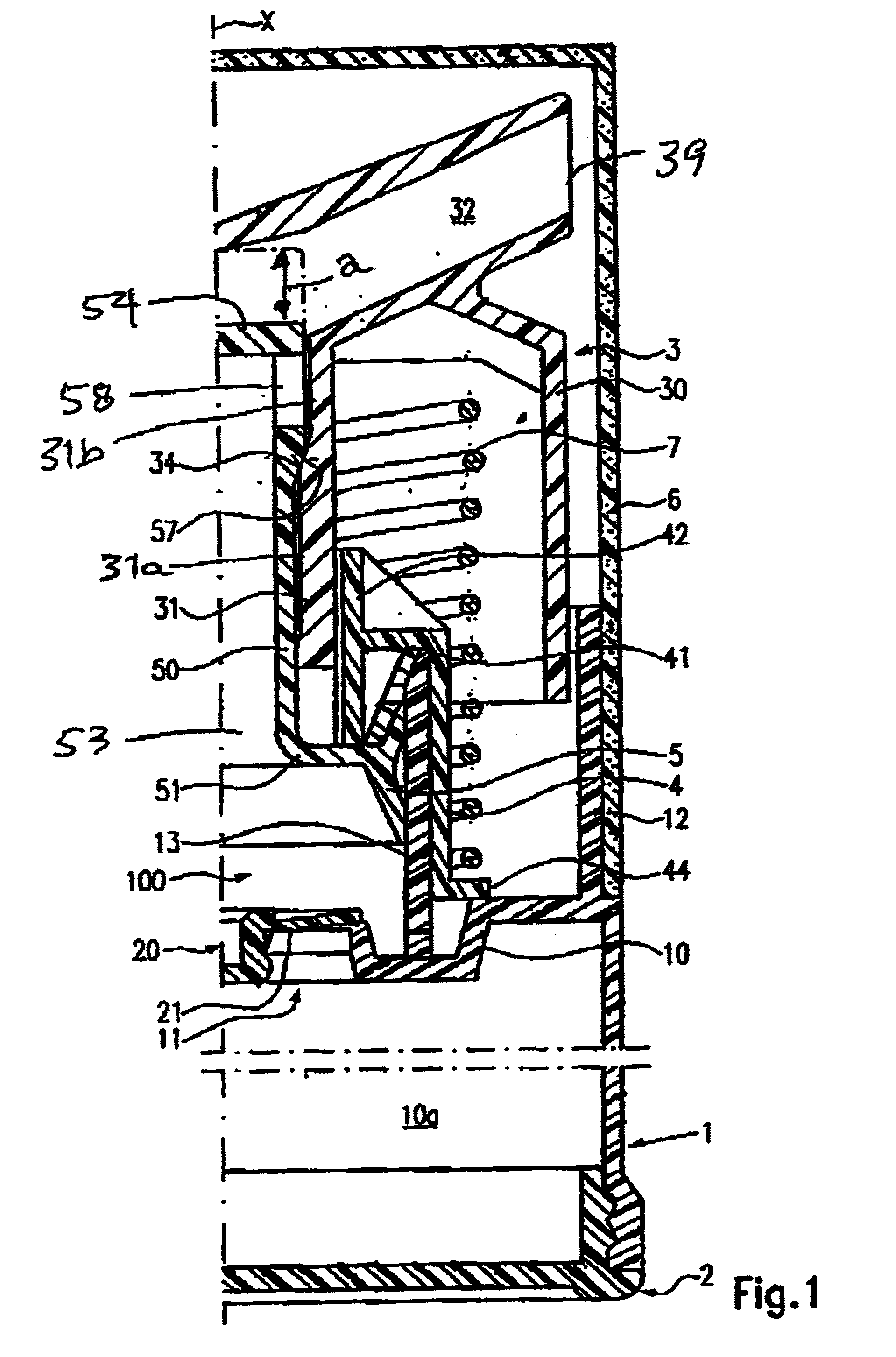
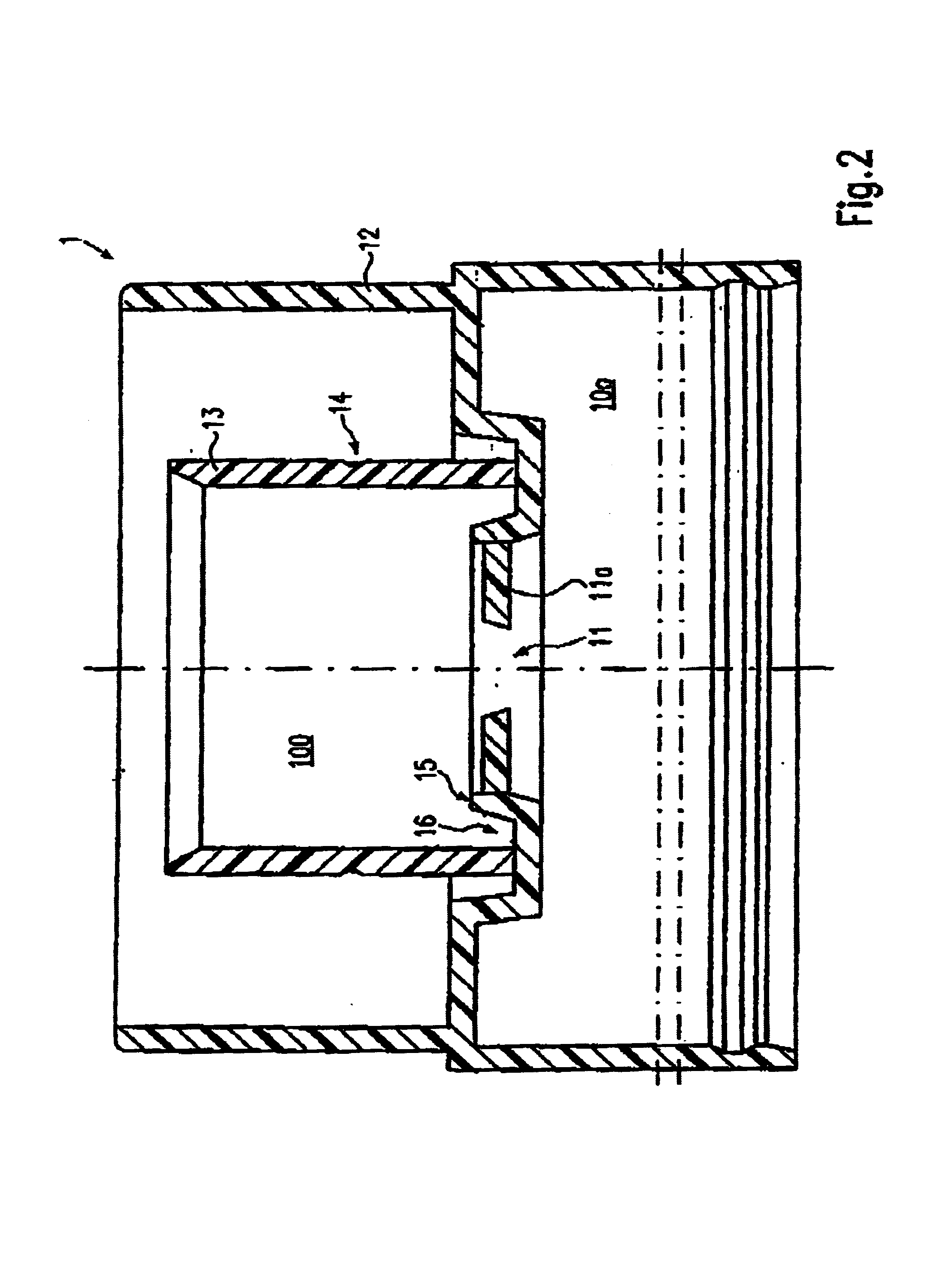
[0056]FIG. 7 shows the dispenser according to the invention. Like parts in this embodiment are designated with like reference numerals in comparison with the above-discussed embodiment. The container 1 of the embodiment shown in FIG. 7 is essentially identical with the container described above, comprising an outer container wall surrounding an inner chamber 10a in which a follower piston 22 is arranged in a longitudinally displaceable manner and which is closed by a bottom plate 2. In contrast to the previously described embodiment, the container 1 is equipped on its cover at the front side with a surrounding locking ring 17. The mating headpiece 4 is radially extended outwards via the annular shoulder 44 and has a cylindrical outer wall 46 which extends substantially in parallel with the holding cylinder 51 and has a diameter larger than the diameter of the outer casing 30 of the headpiece 3. A locking recess 47 is formed between the outer wall 46 and the holding cylinder 41 at th...

first embodiment

[0059]In the embodiment shown in FIG. 7, another difference over the above-mentioned first embodiment is that the discharge channel 32 has formed therein a closure mandrel 32a which is integrally formed on the headpiece 3. The product discharge opening 39 is ring-like due to the closure mandrel 32a. The product discharge opening 39 is covered in the illustrated embodiment by an annular closure member 60 which is connected as a separate component of a thermoplastic elastomer to the headpiece 3. The closure member 60 in the initial position shown in FIG. 7 rests on the outer circumferential surface and on parts of the front side, but particularly on the circumferential surface of the closure mandrel 32a, thereby sealing the discharge channel 32. Integral with the closure member 60 is a coating 61 which is of the same material as the closure member 60 and which extends over the greatest part of the cover of the headpiece 3 at the front side. A non-slip functional surface is formed on t...


PUM


Abstract

A dispenser includes an improved closure arrangement for sealing the dispenser in such a manner that oxidation of the paste-like product to be dispensed is avoided. The main headpiece is spring biased upwardly toward a first position relative to the container and to the product delivery piston, whereupon the upper end surface of the piston is spaced a given distance from the headpiece, and a cylindrical bearing surface on the headpiece closes the product supply outlets contained in the piston. When the main headpiece is depressed downwardly by the given distance toward an intermediate second position in which the headpiece engages the adjacent piston end surface, the bearing surface on the main headpiece is displaced downwardly to open the piston outlets. Upon further downward displacement of both the headpiece and the delivery piston toward a third position relative to the container, the paste-like product is pumped from the delivery chamber by the delivery piston for discharge via a main product outlet contained in the headpiece.

Description

REFERENCE TO RELATED APPLICATION[0001]This is a continuation of the PCT application No. PCT / EP02 / 04423 filed Apr. 22, 2002, based on the German priority Application No. 201 10 604.3 filed Jun. 29, 2001.FIELD OF THE INVENTION[0002]The present invention relates to a dispenser for paste-like products, the dispenser comprising a substantially cylindrical container which contains the paste-like product and which is equipped at the bottom side with a follower piston, which is slidingly displaceable on an inner wall of the container under pressure of the external atmosphere, and at its upper end carries a headpiece which is slidingly displaceable relative to the container and comprises a discharge channel for the product, which is connectable in communicating fashion to the container, and acts on a manually operable delivery means with a delivery chamber of a variable volume for the productBRIEF DESCRIPTION OF THE PRIOR ART[0003]Dispensers of this type are known as portable supply containe...

Claims


Application Information

Patent Timeline
IPC IPC(8): B05B11/00B65D47/34
CPCB05B11/007B05B11/0072B05B11/3021B05B11/3054B05B11/3074B05B11/0048B05B11/1021B05B11/028B05B11/1054B05B11/1074
Inventor LORSCHEIDT, WILLY
Owner INOTECH KUNSTOFFTECHNIK GMBH
Why Eureka
Try Eureka