Method for the manufacturing of a cladding element for a passenger cabin of a vehicle

a technology for passenger cabins and cladding elements, which is applied in the field of vehicle passenger cabin cladding elements manufacturing, can solve the problems of assembly, time and cost, and achieve the effects of reducing the risk of injury, improving the haptic properties of the proposed cladding element, and pleasing visual

Active Publication Date: 2014-12-25
DIEHL AIRCABIN
View PDF2 Cites 2 Cited by
  • Summary
  • Abstract
  • Description
  • Claims
  • Application Information

AI Technical Summary

Benefits of technology

[0019]According to a further advantageous configuration, in a further method step, a flexible layer is adhesively bonded onto the second layer of the sandwich structure and the material strip extending away therefrom. The flexible layer is advantageously formed from an open-cell foam. Said flexible layer reduces the risk of injury and improves the haptic properties of the proposed cladding element.
[0020]Furthermore, in a further method step, a decorative layer, which covers the visible side of the cladding element, can be adhesively bonded onto the sandwich structure or onto the flexible layer. The decorative layer may be formed from, for example, an artificial leather or from a plastic film. Said decorative layer is expediently water-repellent. The decorative layer imparts to the cladding element a pleasing visual effect.

Problems solved by technology

The attaching of cladding sheets, while maintaining a movement gap of a predefined width, and the subsequent sealing of the movement gap with an elastic material cause an outlay in terms of assembly, time and costs.

Method used


Image

  • Method for the manufacturing of a cladding element for a passenger cabin of a vehicle
  • Method for the manufacturing of a cladding element for a passenger cabin of a vehicle
  • Method for the manufacturing of a cladding element for a passenger cabin of a vehicle

Examples


Embodiment Construction

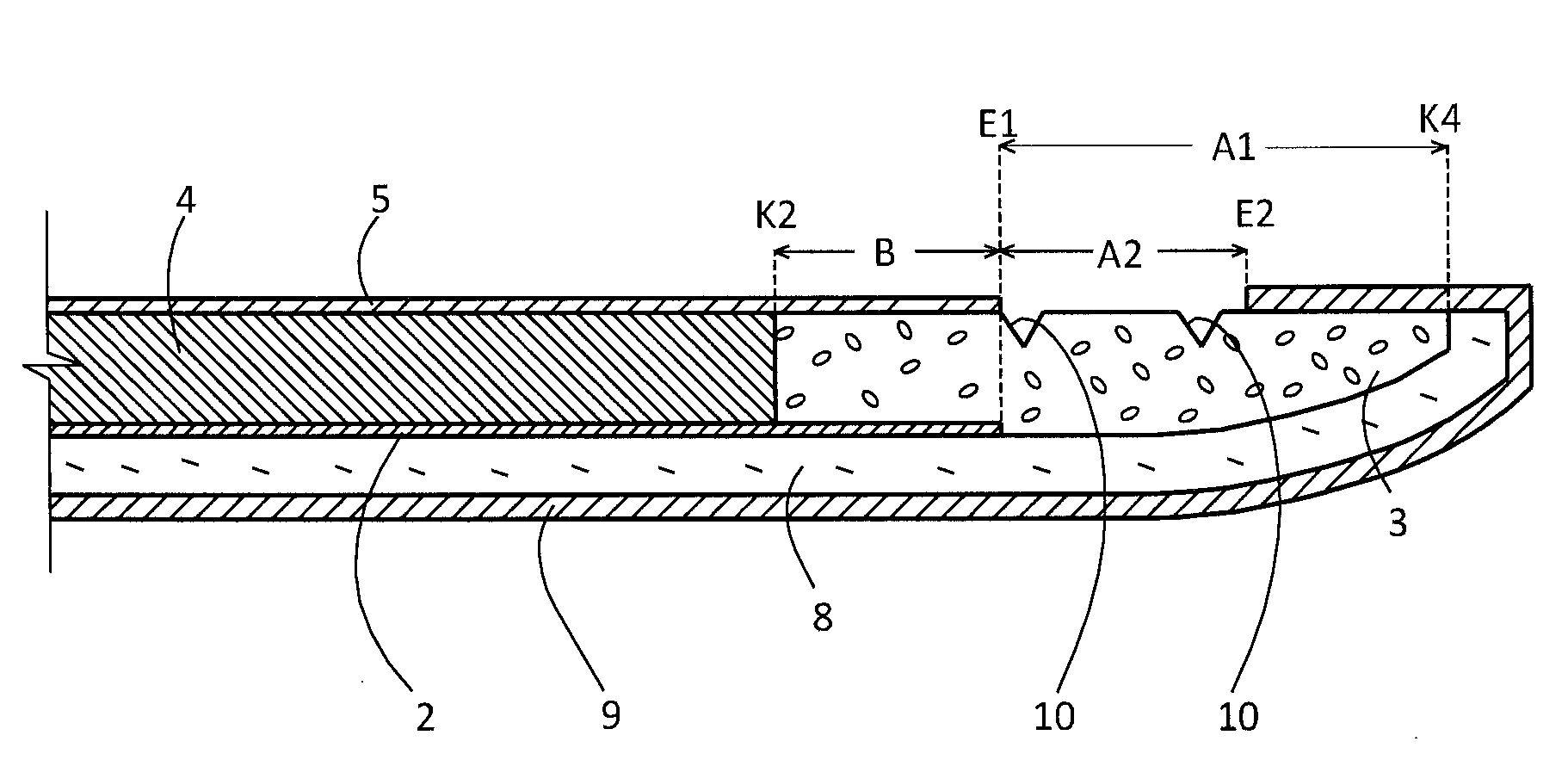
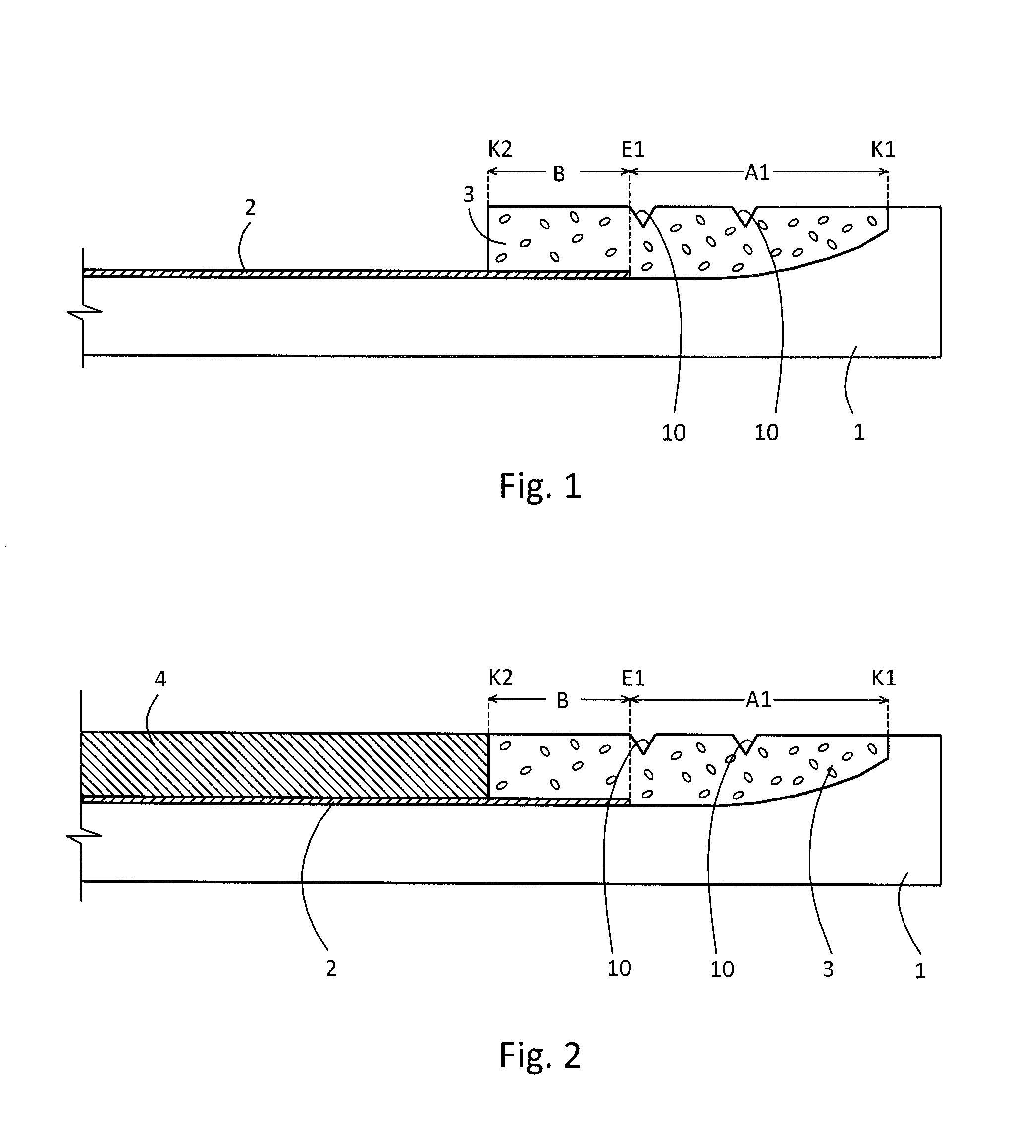
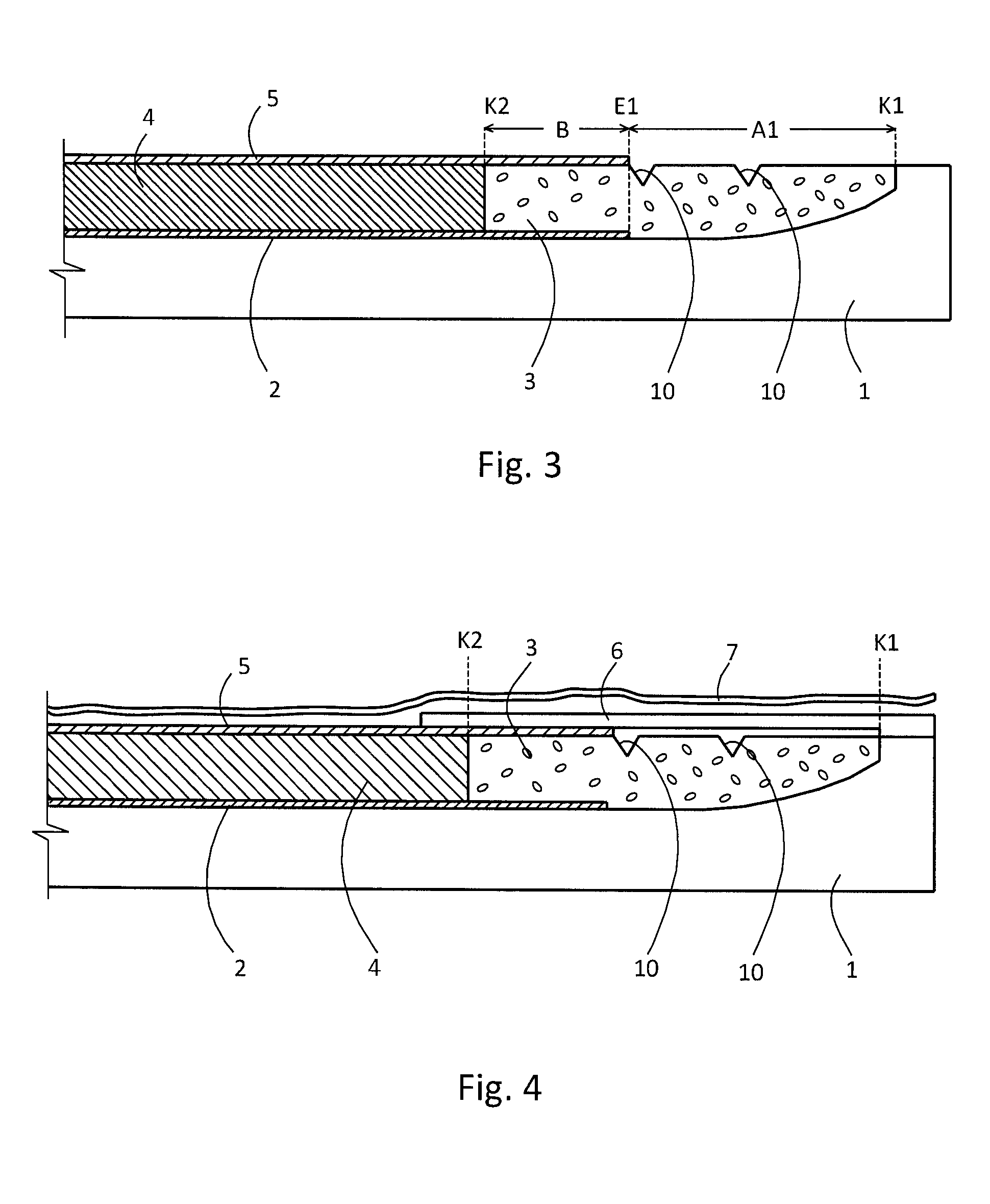
[0028]In FIGS. 1 to 4, a mould, or forming shell, which represents the visible side of the cladding element to be manufactured, is identified with the reference sign 1.

[0029]In a first method step, initially a first prepreg 2 is laid into the forming shell 1. The first prepreg 2 is dimensioned such that a first distance A1 remains between a first edge K1 of the forming shell 1 and an end E1 of the first prepreg 2. The first distance A1 is, for example, 5 to 50 mm, preferably 10 to 30 mm. Thereafter, an elastic material strip 3 is laid into the forming shell 1, and specifically in such a manner that said material strip 3 bears on the first edge K1 of the forming shell 1. The material strip 3 is dimensioned such that, in portions, it superimposes the first prepreg 2. An overlapping portion, which extends from a second edge K2 of the material strip 3 to the end E1 of the first prepreg 2, has a width B. The width B of the overlapping portion may be 5 to 20 mm, preferably 10 to 15 mm.

[00...


PUM

PropertyMeasurementUnit
temperatureaaaaaaaaaa
distanceaaaaaaaaaa

Abstract

The invention relates to a method for the manufacturing of a cladding element for a passenger cabin of a vehicle, in particular of a land vehicle, an aircraft, or a watercraft, comprising the following steps:
introducing a first layer, which is provided with first fibres and impregnated with a resin, into a forming shell,
layering of a support layer, which is sheet-like and reinforced with second fibres, onto the first layer, such that the first layer extends beyond at least one edge of the support layer,
layering of an elastic material strip onto that portion of the first layer that extends beyond the support layer, such that the material strip bears flushly against the edge of the support layer,
layering of a second layer, which is provided with the first fibres and impregnated with the resin, onto the support layer, such that a portion of the second layer extends beyond the edge and lies over the material strip, and
closing the forming shell and exerting a pressure on the layer arrangement, which is accommodated in the forming shell, at a temperature in the region of 50 to 100° C., such that a sandwich structure is formed.

Description

BACKGROUND OF THE INVENTION[0001]The invention relates to a method for the manufacturing of a cladding element for a passenger cabin of a vehicle, in particular of a land vehicle, an aircraft, or a watercraft.DISCUSSION OF THE PRIOR ART[0002]According to the prior art, in particular for the cladding of passenger cabins of aircraft, cladding elements which are manufactured from a lightweight composite material are known. Here, a support layer is laminated between two layers which are provided with fibres and impregnated with a resin. The support layer has a honeycomb structure. Said support layer is typically manufactured from a lightweight material which is reinforced with aramid fibres.[0003]Cladding elements of this type, according to the prior art, are assembled on the inner side of the passenger cabin of an aircraft such that a movement gap remains between the successive cladding sheets, an adjoining bulkhead or the like. Here, the movement gap is dimensioned such that, in the c...

Claims


Application Information

Patent Timeline
Patent Type & Authority Applications(United States)
IPC IPC(8): B29D99/00B29C70/34
CPCB29D99/0021B29C70/34B29L2031/3055B29K2105/0872B29L2031/3076B29K2061/04B29K2611/00B29L2031/3067B29C70/86Y10T156/1044
Inventor SZARSZEWSKI, MAIKHOFFMANN, MATTHIAS
Owner DIEHL AIRCABIN
Why Eureka
Try Eureka