Flow-forced generator with turbo-charging deflection hood

Inactive Publication Date: 2005-10-18
YANG TAI HER
View PDF8 Cites 28 Cited by
  • Summary
  • Abstract
  • Description
  • Claims
  • Application Information

AI Technical Summary

Benefits of technology

[0005]The primary purpose of the present invention is to provide a flow-forced generator adapted with a turbo-charging deflection hood to improve the power of the generator in case of insufficient flow force. To achieve the purpose, an automated directional turbo-charging deflection hood

Problems solved by technology

However, the conventional flow-forced generator driven by turbo is found with the flaw that trade-off takes p

Method used


Image

  • Flow-forced generator with turbo-charging deflection hood
  • Flow-forced generator with turbo-charging deflection hood
  • Flow-forced generator with turbo-charging deflection hood

Examples


Embodiment Construction

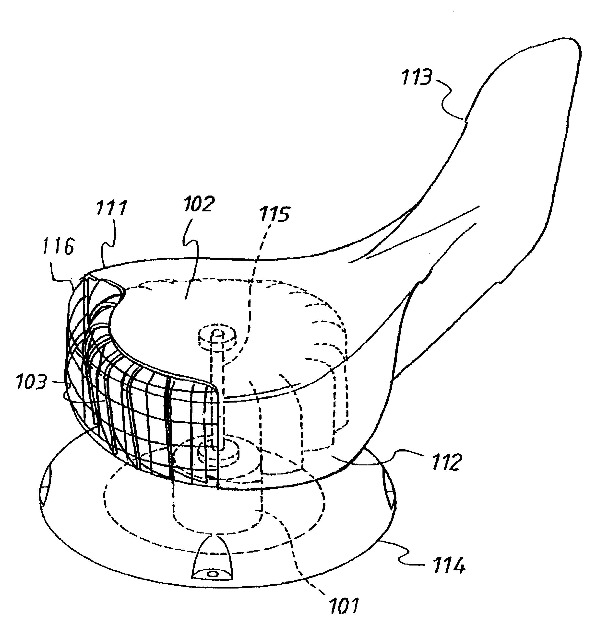
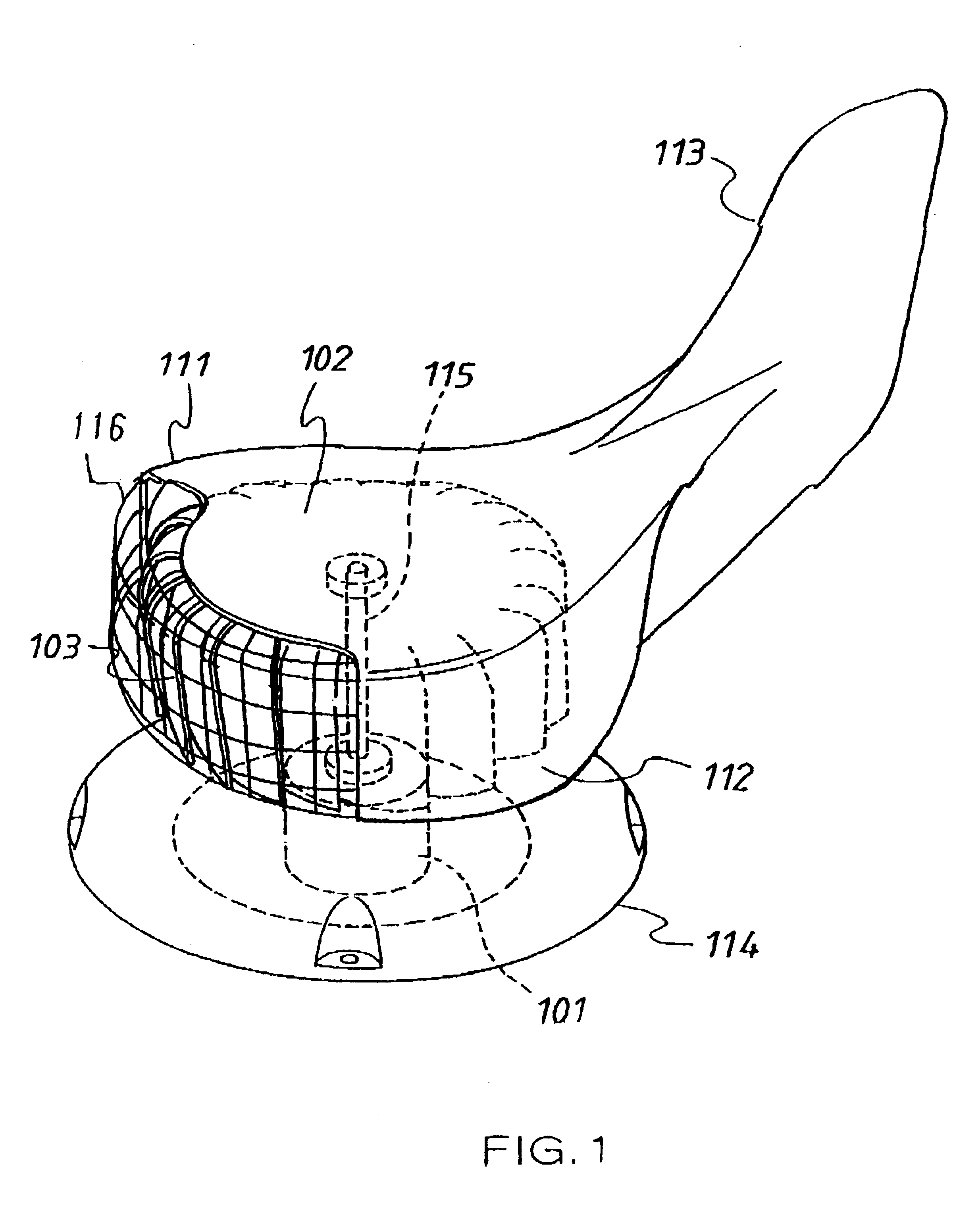
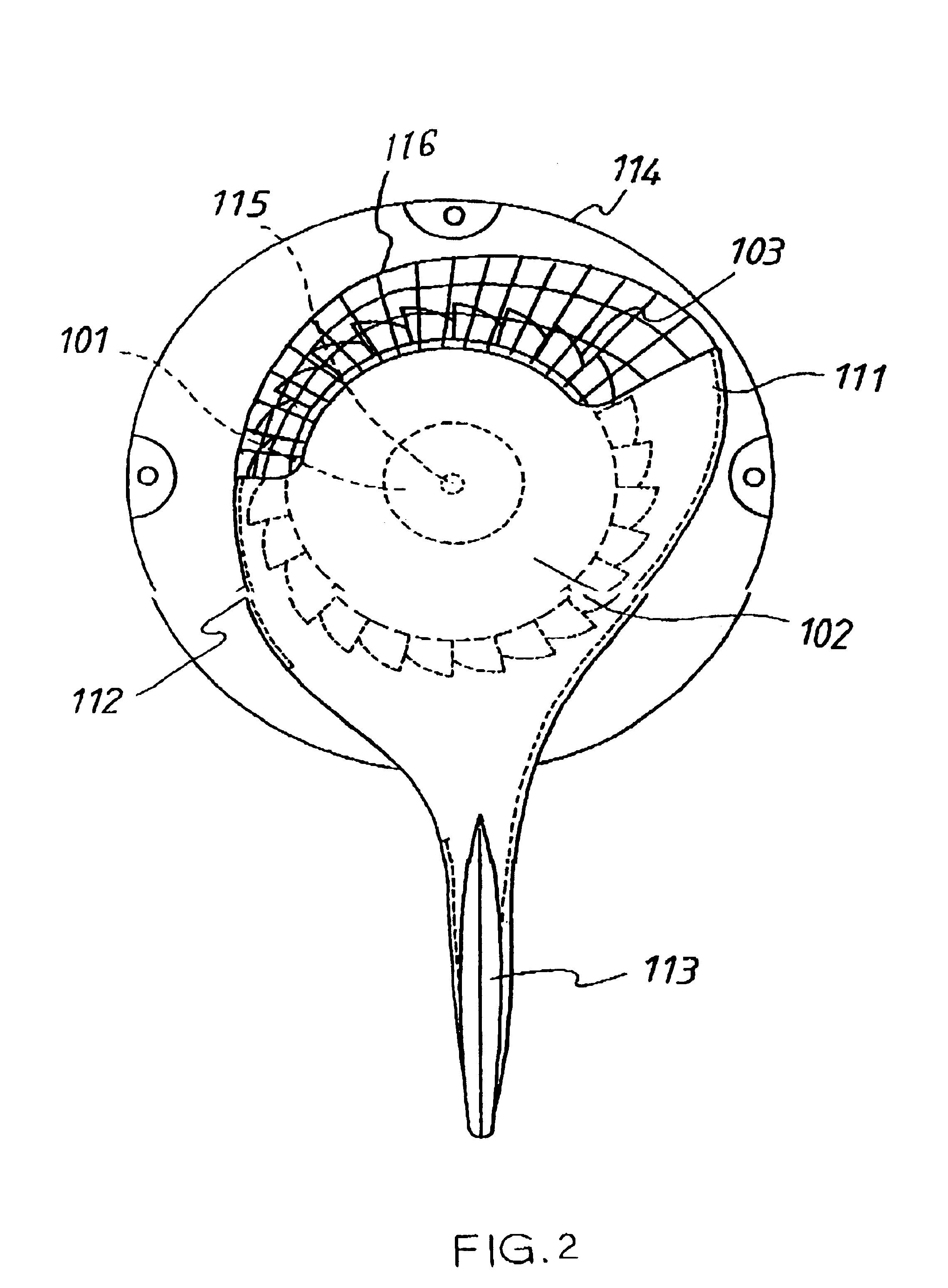
[0015]Referring to FIG. 1 for a perspective view; FIG. 2, a bird's view; and FIG. 3, the side view of a preferred embodiment of the present invention. A flow-forced generator adapted with a turbo-charging deflection hood as illustrated in FIGS. 1, 2, and 3 has the turbo-charging deflection hood 102 adapted to a vortex ring in the flow-forced generator. A flow-forced, directional rudder 113 is provided to the hood 102. The hood is mounted to the peripheral of an automated directional vortex ring to propel the flow-forced generator. Wherein, the air or liquid fluid is guided by an arc deflector 111 provided to the hood 102 for increasing the positive pressure to propel the forced side to create the effect of increased positive pressure, thus to increase the impetus to multiple blades of the vortex ring. Meanwhile, another arc deflector 112 is provided to increase the negative pressure, thus to create the effect of increased negative pressure to the returning side of those vortex ring ...


PUM


Abstract

A flow-forced generator adapted with a turbo-charging deflection hood having at the peripheral of the vortex ring in the generator provided with an automated directional turbo-charging deflection hood for the air or fluid to produce turbo-charging results due to the reducing deflection of the hood, thus to increase the power of the generator in case of insufficient flow force.

Description

BACKGROUND OF THE INVENTION[0001](a) Field of the Invention[0002]The present invention is related to a flow-forced generator adapted with a turbo-charging deflection hood, and more particularly, to one having at the peripheral of the vortex ring in the generator provided with an automated directional turbo-charging deflection hood for the air or fluid to produce turbo-charging results due to the reducing deflection of the hood, thus to increase the power of the generator in case of insufficient flow force.[0003](b) Description of the Prior Art[0004]Whereas the vortex ring does not require directionality, the conventional turbo-driving generator is simple in structure, compact and at lower production cost with a wide range of applications. The turbo structure of most of the flow-forced generators driven by turbo generally available in the market is comprised of multiple are blades in approximately spherical shape. The gas or liquid fluid pushes each of the forced side of those blades...

Claims


Application Information

Patent Timeline
IPC IPC(8): F03D3/04F03D3/00
CPCF03D3/0445F05B2240/215Y02E10/74Y10S415/907F03D80/70F03D3/0481F03D9/25
Inventor YANG, TAI-HER
Owner YANG TAI HER
Why Eureka
Try Eureka