Flexible stent

a stent and flexible technology, applied in the field of flexible stents, can solve the problems of inability to adjust the design, damage to the interior lining of healthy vessels, and the possibility of inadvertent retention of the stent on plaque deposited on the arterial wall,

Inactive Publication Date: 2005-10-18
CARDINAL HEALTH SWITZERLAND 515 GMBH
View PDF208 Cites 103 Cited by
  • Summary
  • Abstract
  • Description
  • Claims
  • Application Information

AI Technical Summary

Benefits of technology

[0014]It is an object of the invention to provide a stent having an enhanced degree of flexibility.
[0022]In addition, in the present embodiment described, adjacent radially rings start out of phase in the unexpanded state. Due to the diagonal orientation of the connection points of the flexible connectors, upon expansion the radial rings tend to align themselves (“in” phase.) This results in more uniform cell space and thus improved scaffolding of the vessel. Further, there is described a “wavy” strut configuration, thereby facilitating both a reduced crimp profile for attaching the flexible connectors at or near a strut mid-point and reduced strain upon expansion, due to the strut itself contributing to a portion of the expansion.

Problems solved by technology

Although a number of stent designs have been reported, these designs have suffered from a number of limitations.
This design has at least one important disadvantage, for example, according to this design, protruding edges occur when the stent is flexed around a curve raising the possibility of inadvertent retention of the stent on plaque deposited on arterial walls.
This may cause the stent to form emboli or move out of position and further cause damage to the interior lining of healthy vessels.

Method used


Image

  • Flexible stent
  • Flexible stent
  • Flexible stent

Examples


Embodiment Construction

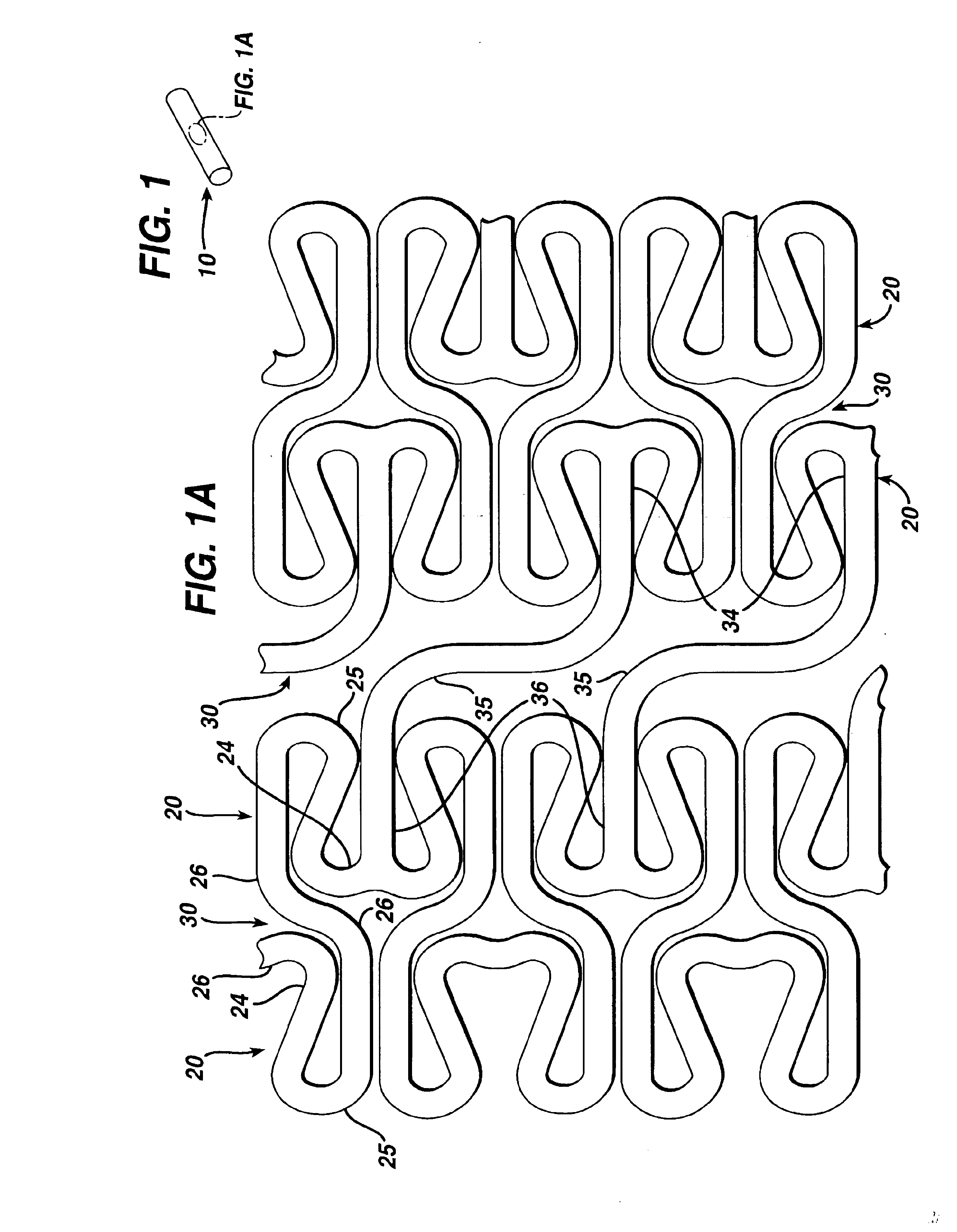
[0034]As can be seen in FIG. 1, there is described a cylindrical stent 10 which has a series of folded strut sections 20 connected by a series of flexible sections 30. The folded strut sections 20 comprise a generally folded strut member 25 having a pair of ends 24, 26. Each of the pair of ends 24, 26 is connected to another folded strut member 25 and also to the end of a flexible member 35. Thus, each end 34, 36 of a flexible member 35 is connected to two ends 24, 26 of a folded strut 25 section member.

[0035]Each of the folded struts 25 takes on a generally irregular pattern. On the other hand, each of the flexible sections 35 takes on a generally undulating pattern. The folded strut sections 20 wrap circumferentially around the cylindrical shape of the stent 10. Each flexible section 30 also connects to a folded strut section 20 around the circumference of the stent. It will be noticed that each adjacent flexible section 30 is positioned 180° out of phase with each other.

[0036]The...


PUM


Abstract

A stent provides a folded strut section that provides both structural rigidity and reduction in foreshortening of the stent mechanism. A flexible section provides flexibility for delivery of the stent mechanism. In a second embodiment, flexible section columns are angled with respect to each other, and to the longitudinal axis of the stent. These relatively flexible sections are oppositely phased in order to negate any torsion along their length. In yet another embodiment, the flexible connector can take on an undulating shape (like an “N”), but such that the longitudinal axis of the connector is not parallel with the longitudinal axis of the stent. Finally, a new method is disclosed for making stents.

Description

CROSS REFERENCE TO RELATED APPLICATIONS[0001]This application claims benefit of Ser. No. 60 / 272,696, filed Mar. 1, 2001, now abandoned.BACKGROUND ART[0002]A stent is commonly used as a tubular structure left inside the lumen of a duct to relieve an obstruction. Commonly, stents are inserted into the lumen in a non-expanded form and are then expanded autonomously (or with the aid of a second device) in situ. A typical method of expansion occurs through the use of a catheter mounted angioplasty balloon, which is inflated within the stenosed vessel or body passageway, in order to shear and disrupt the obstructions associated with the wall components of the vessel and to obtain an enlarged lumen.[0003]In the absence of a stent, restenosis may occur as a result of elastic recoil of the stenotic lesion. Although a number of stent designs have been reported, these designs have suffered from a number of limitations. These include restrictions on the dimension of the stent.[0004]Other stents...

Claims


Application Information

Patent Timeline
Patent Type & Authority Patents(United States)
IPC IPC(8): A61F2/06A61F2/90
CPCA61F2/91A61F2/915A61F2002/91508A61F2002/91516A61F2002/91525A61F2002/91533A61F2002/91558A61F2002/91566A61F2002/91575A61F2230/0054
Inventor MAJERCAK, DAVID C.HOJEIBANE, HIKMATBURGERMEISTER, ROBERT
Owner CARDINAL HEALTH SWITZERLAND 515 GMBH
Why Eureka
Try Eureka