

Method and device for vaporization injection of high volumes in gas chromatographic analysis
a gas chromatographic analysis and high volume technology, applied in the direction of material analysis, components, instruments, etc., can solve the problems of loss of the most volatile compounds, exceedingly difficult to satisfy the conditions, and almost impossible conventional splitless injection
- Summary
- Abstract
- Description
- Claims
- Application Information
AI Technical Summary
Benefits of technology
Problems solved by technology
Method used
Image

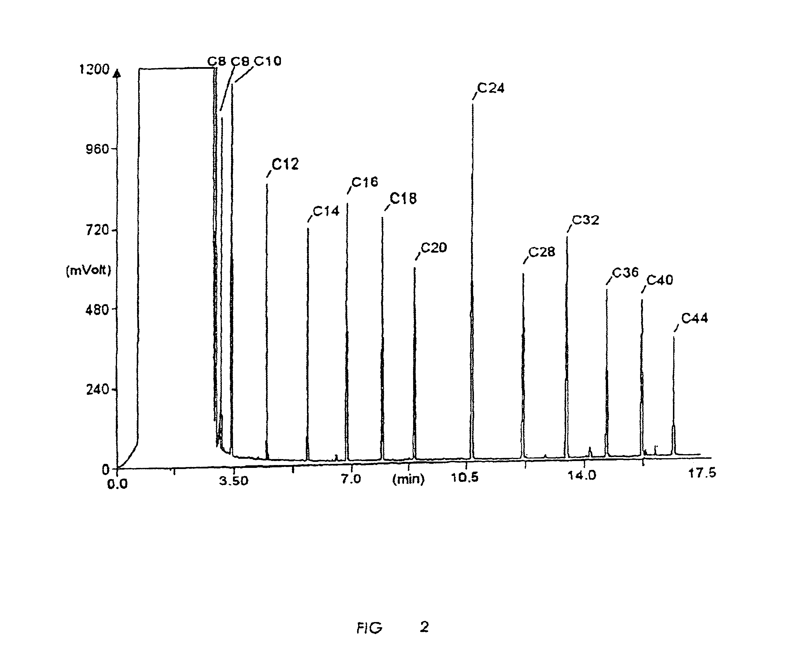
Examples
Embodiment Construction
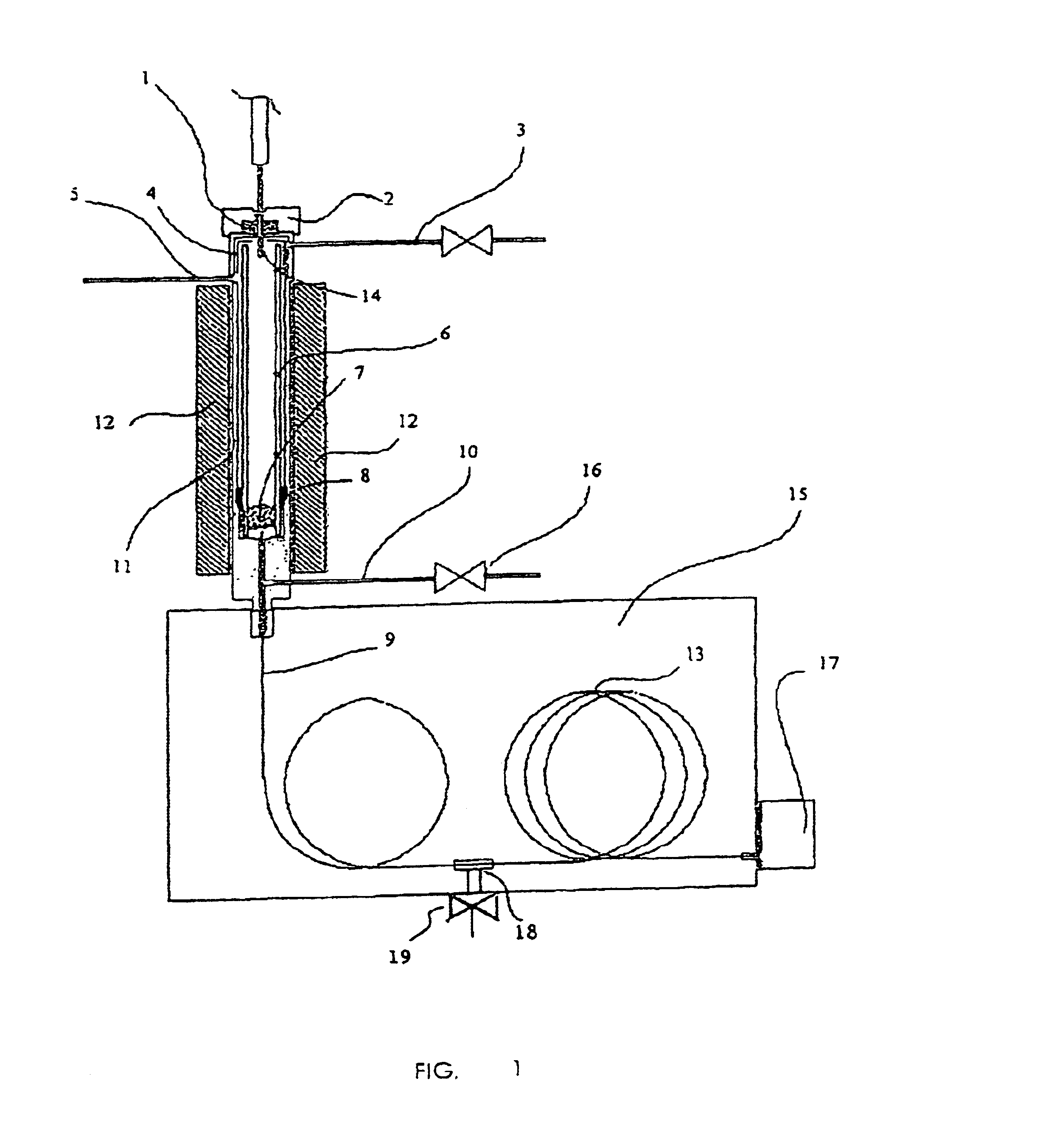
[0022]With reference to FIG. 1, the body of an injector 11 houses a vaporization chamber 6 over which a septum 1 is positioned fixed to the injector by a sealing element 2.
[0023]The vaporization chamber 6 is heated preferably only in the lower portion thereof by well known heating elements 1.2, while the upper portion, closed by a cap 4, is preferably not heated.
[0024]The injector has a duct 5 for feeding the carrier gas and a duct 3 used to clean the septum by means of the carrier. The vaporization chamber is fixed to the injector body by means of a seal 8. The duct 10 schematically indicates a splitting line, with a related valve 16. The sample, taken using known techniques, is introduced into the chamber by means of a syringe, the needle 14 of which, in case smaller than conventional needles, perforates the septum 1 to reach a predetermined point in the chamber and inject the sample in liquid state as a “band” jet which travels the rest of the highly heated vaporization chamber a...
PUM
| Property | Measurement | Unit |
|---|---|---|
| volume | aaaaa | aaaaa |
| volume | aaaaa | aaaaa |
| internal diameter | aaaaa | aaaaa |
Abstract
Description
Claims
Application Information