
Method and device to apply cord thread or ribbons onto fabrics in a quilting machine

a quilting machine and cord thread technology, applied in the direction of embroidering machines, automatic machines, embroidering machines, etc., can solve the problems of limited productivity, discontinuous, and large distance between ornamental designs made by these devices, and achieve thicker and more continuous patterns. , the effect of speed

Inactive Publication Date: 2005-10-25
MECA
View PDF11 Cites 27 Cited by
  • Summary
  • Abstract
  • Description
  • Claims
  • Application Information

AI Technical Summary

Benefits of technology

[0030]A further purpose is to achieve a quilting machine including the device described above, suitable to continuously work fabrics, simple and padded, obtaining any ornamental design whatsoever of the stitches by means of electronic control.
[0033]The co-operation between the needles, each of which is fed with its own thread called needle thread, and the lower sewing elements causes stitches to be made on the fabric, fed continuously from rolls and located between the sewing organs.
[0052]A variant of the invention provides that, during the application of the ribbon or cord thread, the rotation of the movable part may be interrupted on command at pre-determined points of the pattern being formed, in a position such that it does not create interference with the sewing needle, and subsequently re-started at other points. In this way, we achieve segments where the ribbon or cord thread is applied in alternation with segments of simple sewing with the needle thread, in order to achieve ornamental designs characterized by such alternation.
[0055]With the device according to the invention it is possible to apply ribbon, cord thread or similar onto continuously fed fabric, according to the pattern made by the machine, with a much higher speed and with much thicker and more continuous patterns compared with those made in any other type of machine known in the state of the art, with an obvious advantage in terms of productivity and variety of application.

Problems solved by technology

These devices serve to make particular types of embossed embroidery; they work on pieces of a limited length, particularly on pieces worked on the tambour frame, in a discontinuous work pattern which gives limited productivity.
Moreover, the ornamental designs made by these devices are isolated, considerably distant from each other and discontinuous.
When these devices are used the embroidery machines have a very low working speed, in the region of 120 stitches a minute at most.
State of the art devices of this type, as they are used at present, are therefore not suitable for use on electronically controlled machines which continuously work fabric supplied from a roll, with speeds of at least 450 stitches a minute and which can reach up to 600+700 stitches a minute.
Moreover, whereas in embroidery machines the fabric is cut into pieces, attached manually onto appropriate frames before the embroidery operation, and removed always manually when the work is finished, in quilting machines the fabric or the sandwich of material which is to be quilted is unwound continuously from rolls, with a huge saving in time and effort for the workers.
Conventional devices, moreover, do not give the possibility of carrying out step by step, with the position of the wheels, the desired program of embroidery; therefore they do not allow to achieve designs of absolute precision with the cord threads, ribbons or additional threads; nor do they allow to alternate on command segments where the cord thread or ribbon is applied with segments of simple stitching to achieve particular ornamental patterns according to a pre-determined sewing program.
In conventional devices, moreover, it is not always possible, at every step of the program, to direct the hole through which the embroidery thread passes perfectly in front of the needle according to the direction of sewing, with discrepancies of a fraction of a degree; nor is it possible to exclude the alternate rotation of the wheels.
This does not allow these conventional devices to sew exactly in the center, whatever may be the direction of sewing, ribbons, tapes and flat trimmings and to attach them on the basic fabric, nor to alternate segments where ribbon or cord thread is applied with segments of simple stitching, thus limiting the applications and possibilities.

Method used


Image

  • Method and device to apply cord thread or ribbons onto fabrics in a quilting machine
  • Method and device to apply cord thread or ribbons onto fabrics in a quilting machine
  • Method and device to apply cord thread or ribbons onto fabrics in a quilting machine

Examples


Embodiment Construction

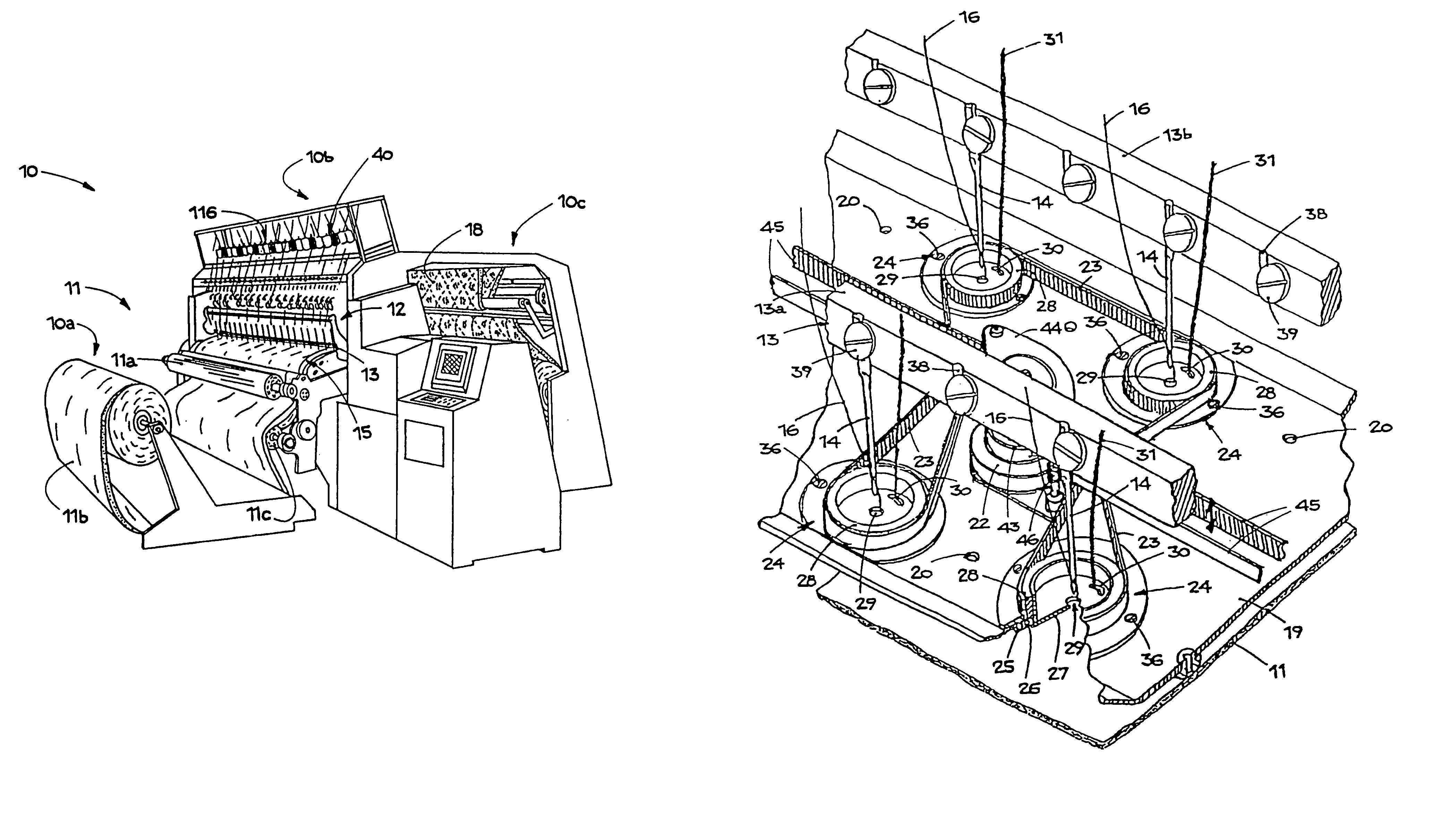
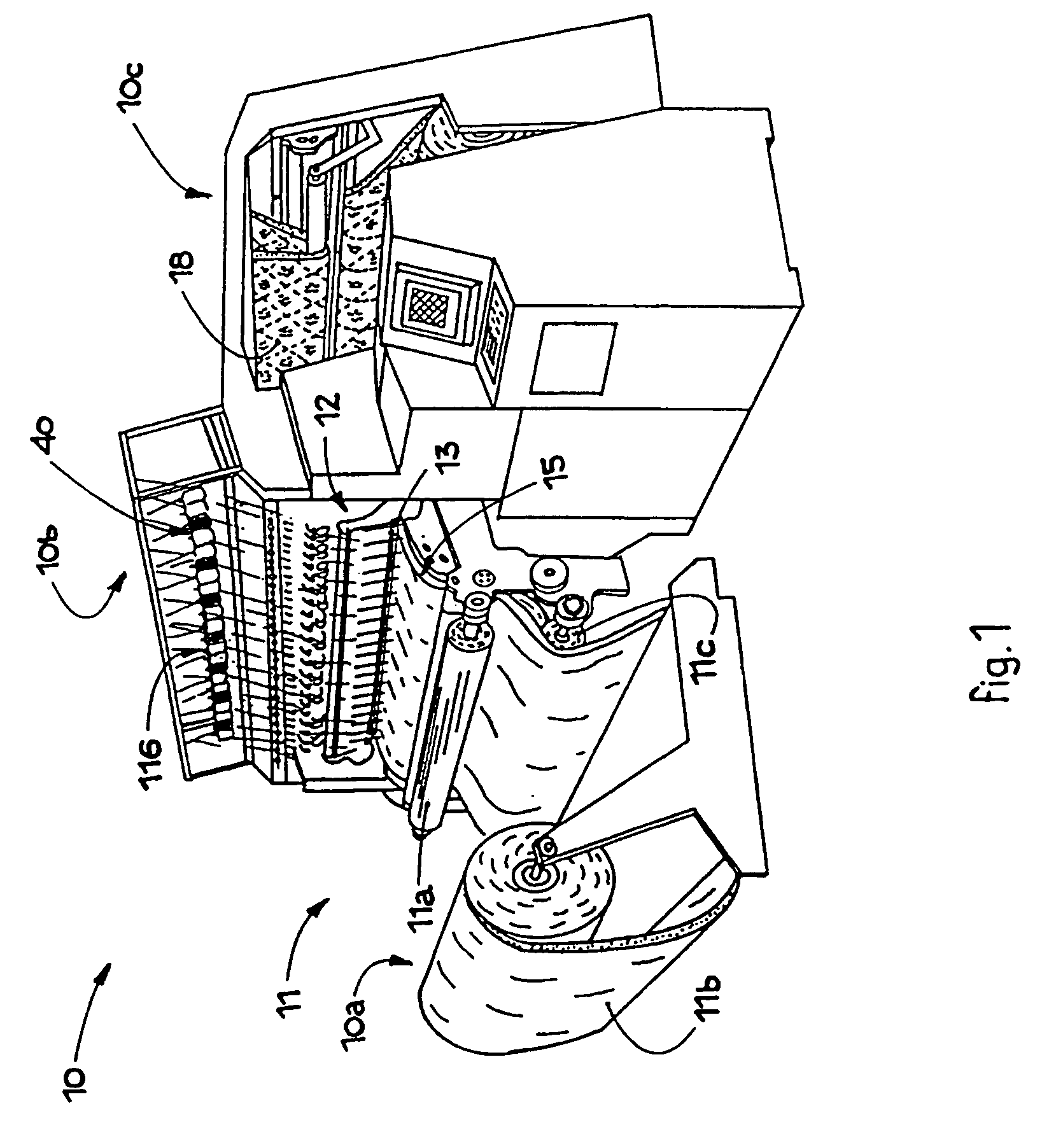
[0064]FIG. 1 shows an electronically controlled multi-needle quilting machine 10 of a general type which is substantially known. The quilting machine 10 comprises, as its essential parts, an inlet assembly 10a, a sewing assembly 10b and an outlet assembly 10c.

[0065]The inlet assembly 10a is used to feed the textile material 11 which has to be worked. The inlet assembly 10a is managed and controlled by software and is therefore able to move the textile material 11 in any direction whatsoever, to-and-fro or right-left, in order to achieve any type of pattern, even extremely complex ones.

[0066]The sewing assembly 10b comprises upper sewing organs 12 and lower sewing organs 15 of a conventional type.

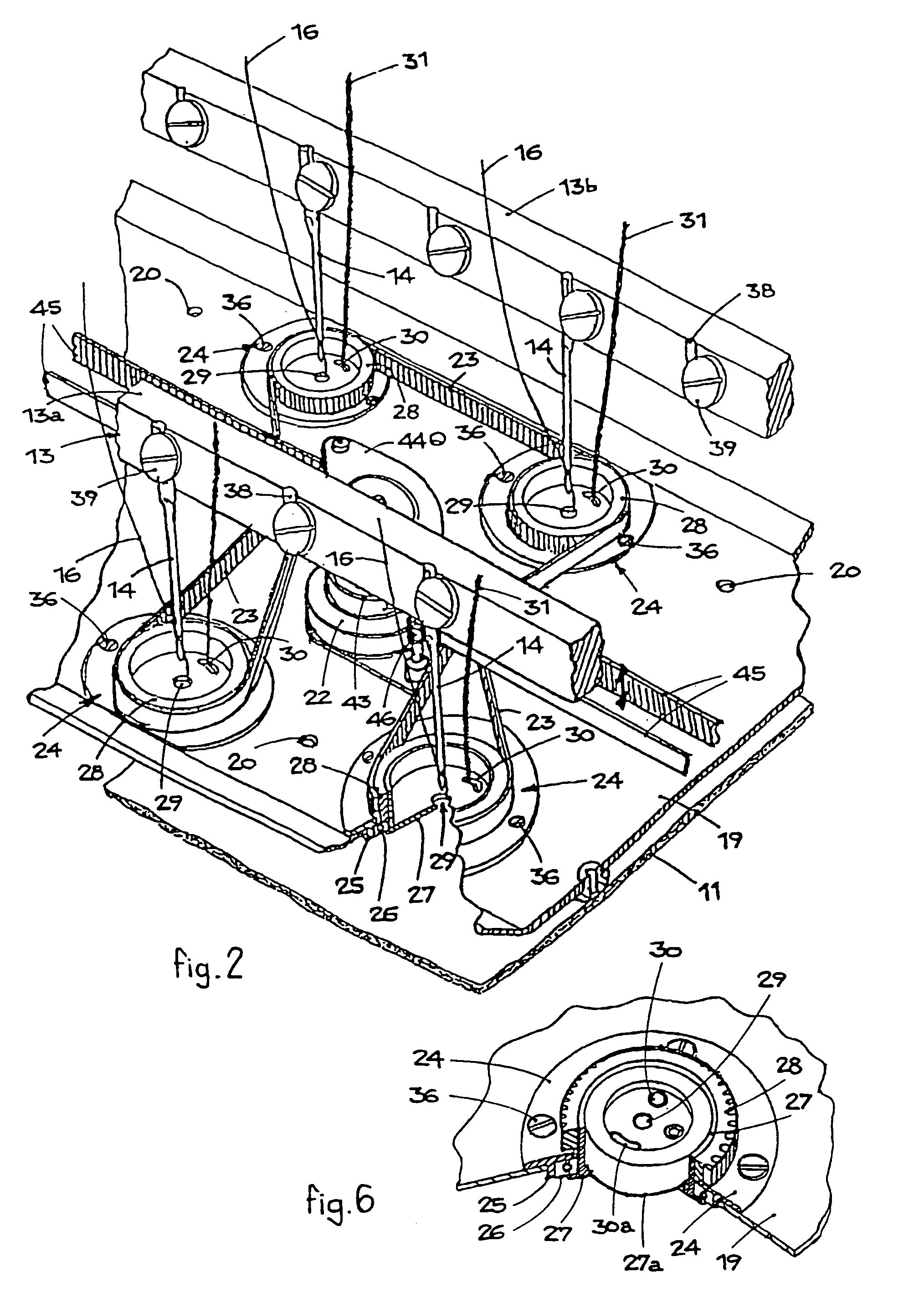
[0067]The upper sewing organs 12 consist, in this case, of two parallel needle-bearing bars 13, respectively 13a and 13b, on which respective aligned needles 14 are assembled, each co-operating with a respective thread 16, called the needle thread, fed from respective reels 116 arranged in ...


PUM


Abstract

A device for applying an embroidery material onto a textile fabric including a device for feeding the textile material; an upper sewing organ having a needle bearing bar and a plurality of needles; a lower sewing organ selected from the group consisting of shuttles, rotary crochets and moving hooks cooperating with the upper organ. At least one pressure plate for compressing the material and having embroidery devices thereon and a drive for providing rotational motion to the embroidery devices, wherein the drive device includes a hole for each needle to pass through and a second hole for the embroidery material to pass through, and wherein the rotational motion is in a single direction so as to direct the second hole in a position that is in front of the needle to obtain stitches on the textile fabric and to fix the embroidery material.

Description

FIELD OF THE INVENTION[0001]This invention concerns a device to apply cord thread or ribbons onto fabrics, simple or padded, in a quilting machine.[0002]The invention also concerns a quilting machine, advantageously but not exclusively a multi-needle machine, equipped with this device.[0003]The invention also concerns a method to apply a ribbon or cord thread onto fabrics, simple or padded, both continuously and also alternated with segments of simple sewing, in a quilting machine.[0004]The invention is applied in the textile field and refers to the automatic application, by means of stitches suitable to achieve a desired pattern or ornamental design, of a cord thread, ribbon or trimming onto simple, multi-layer or padded fabrics fed continuously from rolls.[0005]The invention is applied preferentially, but not exclusively, to multi-needle quilting machines, of the type which makes both knotted stitches and chain stitches.[0006]The invention is characterized by the fact that it incl...

Claims


Application Information

Patent Timeline
Patent Type & Authority Patents(United States)
IPC IPC(8): D05C7/00D05C7/08D05B11/00
CPCD05C7/08
Inventor LANDONI, GIANNINO
Owner MECA
Learn More