

Front body structure for vehicle
- Summary
- Abstract
- Description
- Claims
- Application Information
AI Technical Summary
Benefits of technology
Problems solved by technology
Method used
Image

Examples
second embodiment
[0075]FIG. 13 is a perspective view of the power unit. FIG. 14 is a schematic plan view showing the deformation mode of the front part on the right side of the vehicle body at a small-overlap collision. In the front body structure of the second embodiment, the power unit P is provided with projections 40 each of which engages with a peak part 22a of the folding deformation when the sub-side member 20 is folded inwardly in the width direction of the vehicle due to a vehicle collision.
[0076]Each of the projections 40 is formed to have a L-shaped section and includes an abutting face 41 directing outwardly to interfere with the peak part 22a and an attachment face 42 fitted to the power unit P by means of bolts. The projections 40 are fixed on both sides of a front face Pf of the power unit P while directing the abutting faces 41 outwardly in the width direction of the vehicle.
[0077]The abutting face 41 is formed with a predetermined length in the vertical direction so as to enable rel...
third embodiment
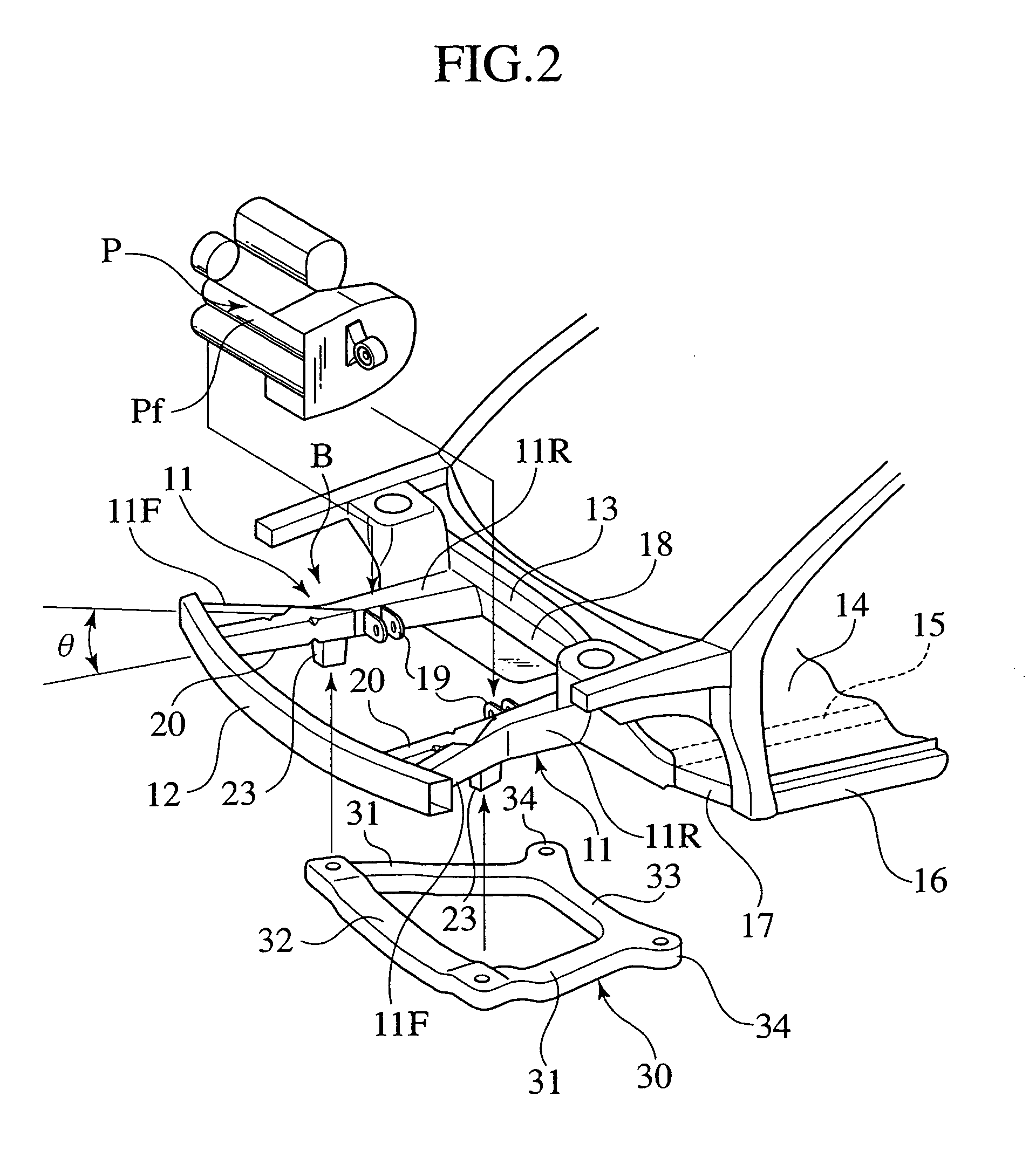
[0080]FIG. 15 is an enlarged perspective view of the skeletal structure of the front part on the right side of the vehicle body. the side-member front area 11F and the side-member rear area 11R are separable from each other. The rear end of the side-member front area 11F is detachably connected with the reinforcing part A for the side member 11, while the sub-side member 20 is formed in one body with the side-member rear area 11R continuously.
[0081]The side-member front area 11F is provided, at the rear end, with a flange 11Ff whose both sides of upper / lower portions are joined to upper and lower flanges Af of the reinforcing part A through bolts, nuts, etc.
[0082]The flange 11Ff is slanted to the side-member front area 11F with an inclination angle θ. Thus, when the flange 11Ff is joined to the reinforcing part A, the side-member front area 11F is inclined outwardly in the width direction of the vehicle with the predetermined angle θ.
[0083]The deformation-mode control mechanism D f...
first embodiment
[0084]Also in this embodiment, the above distance DX is more than a clearance DY (see FIG. 3) between the inside face 20a and the side face of the power unit P, as similar to the
[0085]In addition to the effects of the first embodiment, owing to the above-mentioned relationship among the side-member front area 11F, the side-member rear area 11R and the sub-side member 20, that is, the structure obtained by adding the side-member front area 11F to the front part of the side member 11 serving as a sub-side member F, it is possible to reduce an alternation in design of this structure from the conventional vehicle structure, whereby the front body structure of this embodiment is applicable for broader kinds of vehicles.
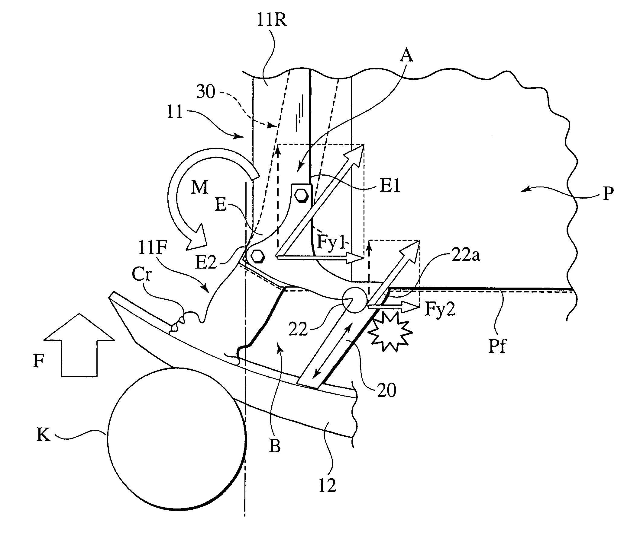
[0086]Owing to the constitution of the deformation-mode control mechanism D, the collision input F (see FIG. 9) allows the sub-side member 20 to be folded in a substantial-V shaped manner stably, as similar to the first and second notches 21, 22 of the first embodiment.
[00...
PUM
 Abstract
Description
Claims
Application Information