Image display device

Active Publication Date: 2006-02-23
PANASONIC LIQUID CRYSTAL DISPLAY CO LTD +1
View PDF2 Cites 2 Cited by
  • Summary
  • Abstract
  • Description
  • Claims
  • Application Information

AI Technical Summary

Benefits of technology

[0021] The present invention reduces the amount of deformation produced in the long-side and short-side portions of the support frame by vacuum stresses by making the widths of the long-side and short-side portions of the support frame uniform and curving at least the long-side portions convexly toward the outside of the panel, and therefore the present invention

Problems solved by technology

There have been problems with the image display device disclosed in the above-mentioned Japanese Patent Application Laid-Open Publication No.
Hei 7-302558 in that making only the oute

Method used


Image

  • Image display device
  • Image display device
  • Image display device

Examples


embodiment 1

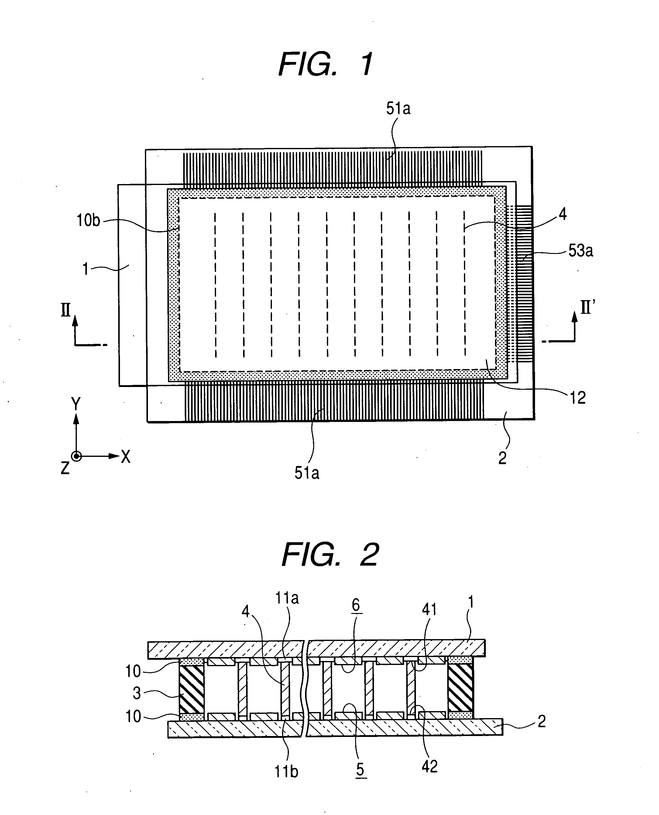
[0034]FIG. 1 is a plan view of a major portion of an electron-emission type display device in accordance with an embodiment of the image display device of the present invention for explaining the rough configuration of the electron-emission type display device, and FIG. 2 is an enlarged cross-sectional view of the major portion of the electron-emission type display device of FIG. 1 taken along line II-II′ of FIG. 1. In FIGS. 1 and 2, reference numeral 1 denotes a front substrate comprised of light-transmissive glass plate, 2 is a rear substrate comprised of a light-transmissive glass plate as in the case of the front substrate, or is comprised of a ceramic plate such as an alumina plate. Consider the front substrate 1 and the rear substrate 2 having a diagonal dimension in a range of from about 32 inches (about 813 mm) to about 50 inches (about 1270 mm). (By way of example, in the case of the substrates of 32 inches in diagonal, the size of the substrates is 800 mm×500 mm.) The thic...


PUM


Abstract

An image display device includes a front substrate having anodes and phosphors, a rear substrate having plural video signal wirings and plural electron sources each formed on a corresponding one of the video signal wirings, and disposed to face the front substrate with a predetermined spacing between the front and rear substrates and a support member which is sandwiched between the front and rear substrates, surrounds a display area formed therebetween and maintains the predetermined spacing. The support member is includes long-side portions of a uniform width disposed on long sides of the front substrate and short-side portions of a uniform width disposed on short sides of the front substrate. At least the long-side portions are curved convexly toward an outside of the display area.

Description

CLAIM OF PRIORITY [0001] The present application claims priority from Japanese application serial no. 2004-242397, filed on Aug. 23, 2004, the content of which is hereby incorporated by reference into this application. BACKGROUND OF THE INVENTION [0002] The present invention relates to an image display device which utilizes emission of electrons into a vacuum produced between a front substrate and a rear substrate, and in particular to a configuration of a support member which seals and supports the front and rear substrates with a desired spacing therebetween. [0003] Conventionally, color cathode ray tubes have been widely used as display devices excellent in producing high-brightness high-definition display devices. However, as the video quality in information processing equipment and TV broadcasts has been improved in recent years, the demand has been becoming stronger for flat panel display devices capable of realizing lighter weight and thinner profile in addition to the perfor...

Claims


Application Information

Patent Timeline
IPC IPC(8): H01J19/42H01J63/04H01J1/62
CPCH01J29/861H01J31/123H01J2329/8675H01J2329/862H01J2329/861
Inventor KIJIMA, YUUICHIHIRASAWA, SHIGEMIINOUE, YUICHIHATORI, AKIRA
Owner PANASONIC LIQUID CRYSTAL DISPLAY CO LTD
Why Eureka
Try Eureka