
Socket for electric component

Active Publication Date: 2008-11-13
ENPLAS CORP
View PDF4 Cites 2 Cited by
  • Summary
  • Abstract
  • Description
  • Claims
  • Application Information

AI Technical Summary

Benefits of technology

[0009]An object of the present invention is to solve the above-described problem by providing a socket for an electric component which is able to positively reduce an amount of deformation of its slide plate that is provided for causing each of plural contact pins arranged inside the socket main body thereof to do a displacement for coming into contact with or separating apart from each of connection terminals of the electric component so that the amount of movement of the slide plate is entirely equalized.
[0011]With the above-described structure, in addition to the drive levers for lowering or descending the slide plate by pressing both end portions on opposing two sides of the slide plate by the operation of the socket cover for causing its down movement, the sub-levers are provided between the socket main body and the bottom face of the socket cover in order to press one position or plural positions of the other opposing two sides of the slide plate to lower the slide plate, thereby surely reducing the amount of deformation of the slide plate. Consequently, the amounts of movements of the side portions and the central portion of the slide plate can be always equalized to prevent occurrence of a contact failure between a contact portion at the tip end of each of the contact pins disposed in the central portion of the slide plate and a corresponding connection terminal portion of the electric component. Further, because the amount of movement of the respective side portions and that of the central portion of the slide plate can be equalized, the present invention can cope with the multiple pin trend of the contact pins of the socket for an electric component.
[0012]The sub-levers are disposed to press the central portion of the side plate in which the deformation of the opposing two sides of the slide plate different from both end portions of the slide plate is larger than that of the latter portions. Consequently, the sub-levers provided for pressing a central portion of the other opposing two sides in which the deformation of the other opposing two sides of the slide plate becomes larger than that of the both end portions of the other opposing two sides press the position suffering from a large deformation of the other opposing two sides of the slide plate to lower the slide plate, thereby reducing an amount of the deformation of the slide plate. Thus, the amounts of the movements of the side portion and the central portion of the slide plate can be equalized to prevent occurrence of a contact failure between the contact portion at the tip end of the contact pins and the connection terminals of the electric component.
[0013]Further, the sub-levers are so constructed to press the other opposing two sides of the slide plate when the amount of deformation of the slide plate becomes larger than a predetermined amount after an instant when the drive levers come to press the opposing two sides of the slide plate. As a result, when the amount of deformation of the slide plate becomes larger than the predetermined amount after the drive levers press the opposing two sides of the slide plate, the sub-levers for pressing the other opposing two sides of the slide plate press the portion in which deformation of the other opposing two sides of the slide plate is large with a time lag with respect to an operation of the drive levers so as to lower the slide plate, thereby reducing the amount of deformation of the slide plate. Therefore, while the deformation of the slide plate is small, the opposing two sides of the slide plate are pressed and lowered by only the drive levers and, when the deformation of the slide plate becomes larger than the predetermined one, the sub-levers press the portion in which the deformation of the other opposing two sides of the slide plate is large so as to lower the slide plate, so that the deformation can be reduced depending on a state how the deformation of the slide plate grows from an initial flat condition.
[0014]Further, the lever motion ratio exhibited by the drive lever to lower the slide plate in response to a downward-movement-operation of the socket cover is set larger than the lever motion ratio exhibited by the sub-lever to lower the slide plate in response to the downward-movement operation of the socket cover. Consequently, operating force at an initial period of operation of lowering the slide plate is reduced by the drive lever capable of exhibiting the lever motion ratio which is larger than the lever motion ratio exhibited by the sub-lever to lower the slide plate in response to the downward movement operation of the socket cover. Additionally, when the amount of the deformation of the slide plate becomes larger than the predetermined one, the sub-levers participate in pressing of the slide plate, so that the slide plate may be smoothly lowered.

Problems solved by technology

If the slide plate 5 is deformed in this way, the moving distance thereof in the vertical direction becomes unequal between the opposing two sides 6, 7 and the central portion therebetween, so that the contact portions at the tip ends of the contact pins disposed at the central portion of the slide plate 5 fail to be sufficiently opened, thereby often causing a contact failure between the contact pin and the connection terminal of the electric component.
Accordingly, the conventional socket for an electric component cannot often cope with the multiple pin configuration trend of the contact pin.

Method used


Image

  • Socket for electric component
  • Socket for electric component
  • Socket for electric component

Examples


Embodiment Construction

[0027]Hereinafter, embodiments of the present invention will be described in detail with reference to the accompanying drawings.

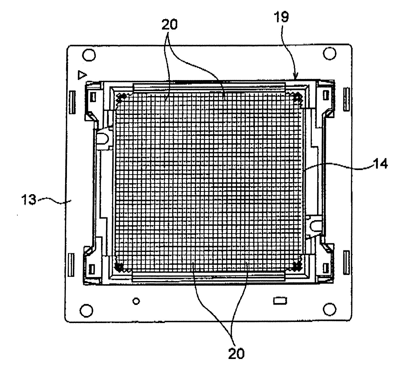
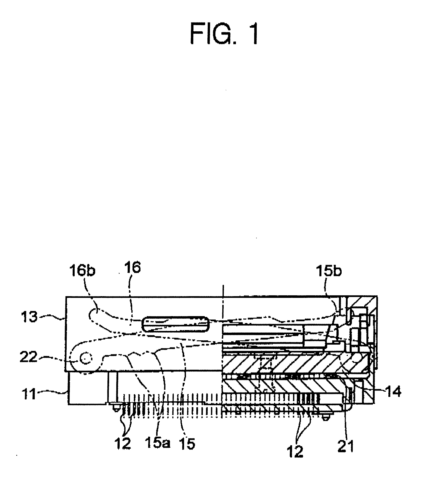
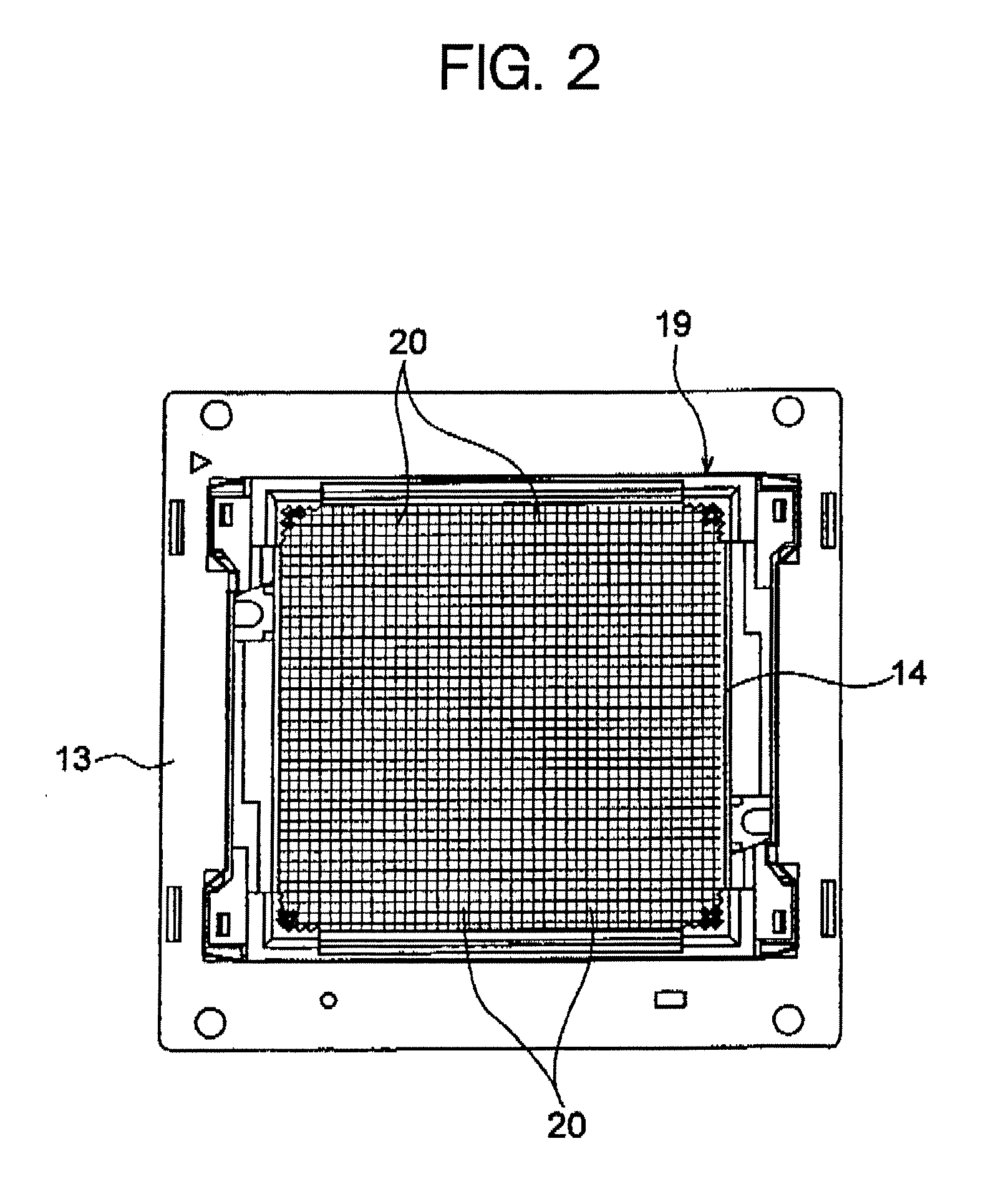
[0028]FIG. 1 is a front view of a right half section showing an embodiment of the socket for an electric component of the present invention, and FIG. 2 is a plan view thereof. This socket for an electric component is adapted for detachably accommodating an electric component such as an IC package or the like to connect that electric component to a circuit board such as a printed wiring board and is, for example, an open-top-type socket, which includes therein a socket main body 11, a contact pin 12, a socket cover 13, a slide plate 14, drive levers 15, 16 and sub-levers 17, 18 (see FIGL 7).

[0029]In an IC package 25 as an electric component, as shown in FIGS. 3A, 3B, a plurality of substantially spherical solder balls 25b as a connection terminal are projected from the bottom face of a rectangular package main body 25a in which a device such as an integrated...


PUM


Abstract

The present invention provides a socket for an electric component having: a socket main body; a plurality of contact pins disposed within the socket main body; a socket cover; a slide plate disposed inside the socket main body to be movable up and down; and drive levers which are provided between the socket main body and the bottom face of the socket cover and press both end portions of two opposing sides of the slide plate by a down-movement-operation of the socket cover to lower the slide plate, wherein sub-levers for pressing one or plural positions of other opposing two sides of the slide plate to lower the slide plate are provided between the socket main body and the bottom face of the socket cover.

Description

BACKGROUND OF THE INVENTION[0001]1. Field of the Invention[0002]The present invention relates to a socket for an electric component, which is adapted for detachably accommodating an electric component such as an IC package or the like to connect the same to a circuit board, e.g., a printed circuit board, and more particularly to a socket for an electric component, which is provided with a plurality of contact pins arranged in a socket main body and a slide plate for permitting each of the plurality of contact pins to be brought into contact with or separated apart from each of connection terminals of the electric component through displacement of the contact pins, and is capable of reducing an amount of deformation of the slide plate for equalizing the amount of movement of the slide plate.[0003]2. Description of the Related Art[0004]Conventionally, this type of the socket for an electric component, in particular, an open-top-type socket includes therein, as shown in FIG. 11, a sock...

Claims


Application Information

Patent Timeline
IPC IPC(8): H05K7/00
CPCH05K7/1007
Inventor KANESASHI, HOKUTO
Owner ENPLAS CORP
Learn More