Electromagnetic locking differential assembly

a technology of electromagnetic locking and differential assembly, which is applied in the direction of mechanical actuated clutches, transportation and packaging, and gearing, etc., can solve the problems of mechanical devices not being selectively disengaged during the operation of anti-lock braking systems or vehicle traction control systems, and the conventional differential mechanism has a deficiency

Inactive Publication Date: 2005-10-25
AMERICAN AXLE & MFG
View PDF35 Cites 75 Cited by
  • Summary
  • Abstract
  • Description
  • Claims
  • Application Information

AI Technical Summary

Problems solved by technology

However, the conventional differential mechanism has a deficiency when a vehicle is operated on a slippery surface.
As a result, the vehicle often becomes immobilized.
Additionally, such mechanical devices may not be selectively disengaged during operation of anti-lock braking systems or vehicle traction control systems.
If a mechanical type limited slip differential is present, independent control of the speed of each wheel coupled to a differential is no longer possible.

Method used


Image

  • Electromagnetic locking differential assembly
  • Electromagnetic locking differential assembly
  • Electromagnetic locking differential assembly

Examples


Embodiment Construction

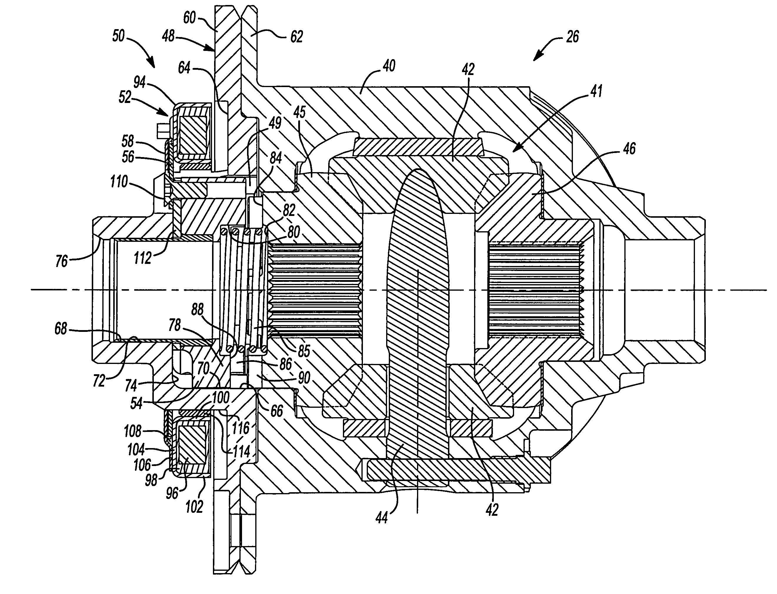
[0013]The present invention is directed to an improved differential for a drivetrain of a motor vehicle. The differential of the present invention includes an actuator operable to place the differential in an “open” or “locked” condition. It should be appreciated that the differential of the present invention may be utilized with a wide variety of driveline components and is not intended to be specifically limited to the particular application described herein. In addition, the actuator of the differential of the present invention may be used in conjunction with many types of differentials such as a bevel gear design which are of a completely open or limited-slip variety.

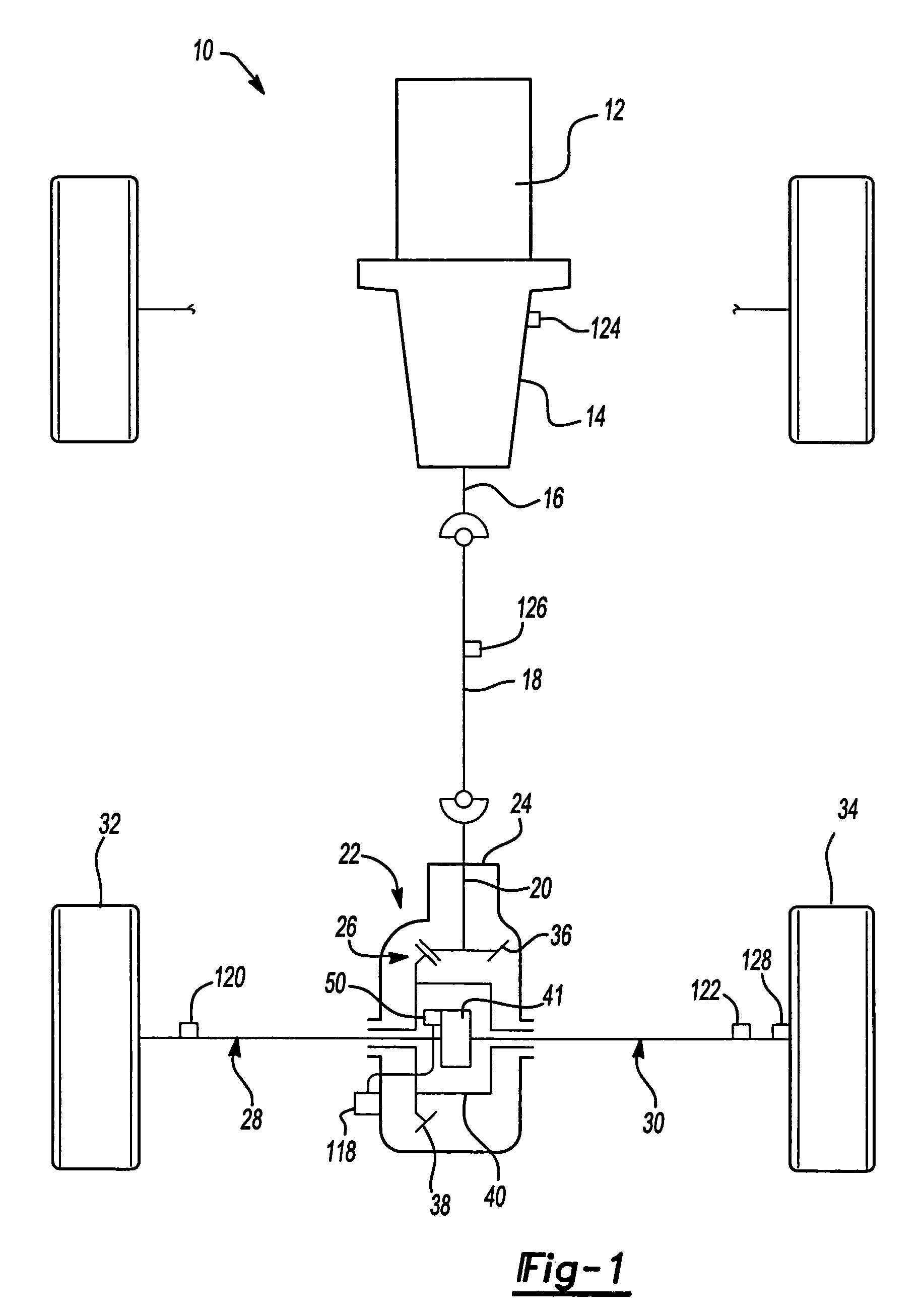
[0014]With reference to FIG. 1, a drivetrain 10 for an exemplary motor vehicle is shown to include an engine 12, a transmission 14, having an output shaft 16 and a propeller shaft 18 connecting output shaft 16 to a pinion shaft 20 of a rear axle assembly 22. Rear axle assembly 22 includes an axle housing 24, a diffe...


PUM


Abstract

A differential assembly includes a case, a pair of pinion gears, a pair of side gears and an electrically operable coupling including an electromagnet. The coupling selectively drivingly interconnects one of the side gears and the case. The electromagnet of the coupling is axially moveable within the case to selectively place the differential assembly in an open or a locked condition.

Description

BACKGROUND OF THE INVENTION[0001]The present invention generally relates to differentials for motor vehicles and, more particularly, to a locking differential employing an electromagnet to control operation of the differential.[0002]As is known, many motor vehicles are equipped with driveline systems including differentials which function to drivingly interconnect an input shaft and a pair of output shafts. The differential functions to transmit drive torque to the output shafts while permitting speed differentiation between the output shafts.[0003]Conventional differentials, such as a parallel-axis helical differential, include a pair of side gears fixed for rotation with the output shafts and two or more sets of meshed pinion gears mounted within a differential case. However, the conventional differential mechanism has a deficiency when a vehicle is operated on a slippery surface. When one wheel of the vehicle is on a surface having a low coefficient of friction, most or all of th...

Claims


Application Information

Patent Timeline
Patent Type & Authority Patents(United States)
IPC IPC(8): F16H48/00F16H48/30F16H48/24F16H48/08F16H48/10F16D27/118F16H48/20
CPCF16H48/08F16H48/10F16H48/11F16H48/24F16H48/30F16H48/34F16H48/40F16H2048/106F16H2048/204F16H2048/346F16H48/20
Inventor DEGOWSKE, ROBERT J.
Owner AMERICAN AXLE & MFG
Why Eureka
Try Eureka