Porous electrode, solid oxide fuel cell, and method of producing the same

a solid oxide fuel cell and porous electrode technology, applied in the manufacture of final products, cell components, electrochemical generators, etc., can solve the problems of inability to prepare cu-ysz cermets, stringent requirements for fabrication materials, and inability to manufacture respective cell components, etc., to achieve high electrode electrical conductivity, high fuel efficiency, and high power

Inactive Publication Date: 2005-10-25
THE TRUSTEES OF THE UNIV OF PENNSYLVANIA
View PDF27 Cites 30 Cited by
  • Summary
  • Abstract
  • Description
  • Claims
  • Application Information

AI Technical Summary

Benefits of technology

[0009]It would be desirable to provide a solid oxide fuel cell that has high fuel efficiency, high electrode electrical conductivity, high power, and is capable of directly oxidizing hydrocarbons. It also would be desirable to provide electrode and cathode materials, and methods of preparing the electrode and cathode materials for use in solid oxide fuel cells, whereby the materials can be fabricated at lower temperatures to avoid solid state reactions.
[0010]A feature of an embodiment of the invention therefore is to provide a solid oxide fuel cell that has high fuel efficiency, high electrode electrical conductivity, high power, and is capable of oxidizing hydrocarbons. An additional feature of embodiments of the invention is to provide porous electrode materials, methods of making the electrode materials, and methods of making the solid oxide fuel cells.
[0015]In accordance with an additional feature of an embodiment of the invention, there is provided a cathode comprising a porous ceramic matrix and an electronically conducting material dispersed at least partially within the pores of the porous ceramic matrix, whereby the cathode was prepared by impregnating the porous ceramic matrix material with precursors to the electronically conducting material and heating the mixture to a temperature high enough to form the conductive phase but low enough to prevent a solid state reaction from taking place between the ceramic matrix and the electronically conducting material.
[0016]In accordance with another feature of an embodiment of the invention, there is provided a method of making a porous cathode comprising forming a porous ceramic matrix, impregnating the porous ceramic matrix with a solution containing precursors to the electronically conducting material, and heating the mixture to a temperature low enough to prevent a solid state reaction from taking place between the ceramic matrix and the electronically conducting material.

Problems solved by technology

The high temperature of the solid oxide fuel cell, however, places stringent requirements on its fabrication materials.
), the materials used to fabricate the respective cell components are limited by chemical stability in oxidizing and reducing environments, chemical stability of contacting materials, conductivity, and thermomechanical compatibility.
Because Cu2O and CuO melt at 1235 and 1326° C. respectively, temperatures below that necessary for densification of YSZ electrolytes, it is not possible to prepare Cu-YSZ cermets by high-temperature calcination of mixed powders of CuO and YSZ, a method analogous to that usually used as the first step to produce Ni-YSZ cermets.
Because the Cu phase in the final cermet must be highly connected, high metal loadings are necessary; and, even then, connectivity between all Cu particles in the anode structure is not assured.
Since YSZ powders do not sinter to a significant extent appreciably below 1100° C., the conditions for achieving optimal electrode properties from oxide composites are rather limited.
Indeed, it is not possible to prepare some oxide composites due to the fact that the sintering temperature for YSZ is higher than the temperature at which solid-state reactions occur between the two oxides.

Method used


Image

  • Porous electrode, solid oxide fuel cell, and method of producing the same
  • Porous electrode, solid oxide fuel cell, and method of producing the same
  • Porous electrode, solid oxide fuel cell, and method of producing the same

Examples


example 1

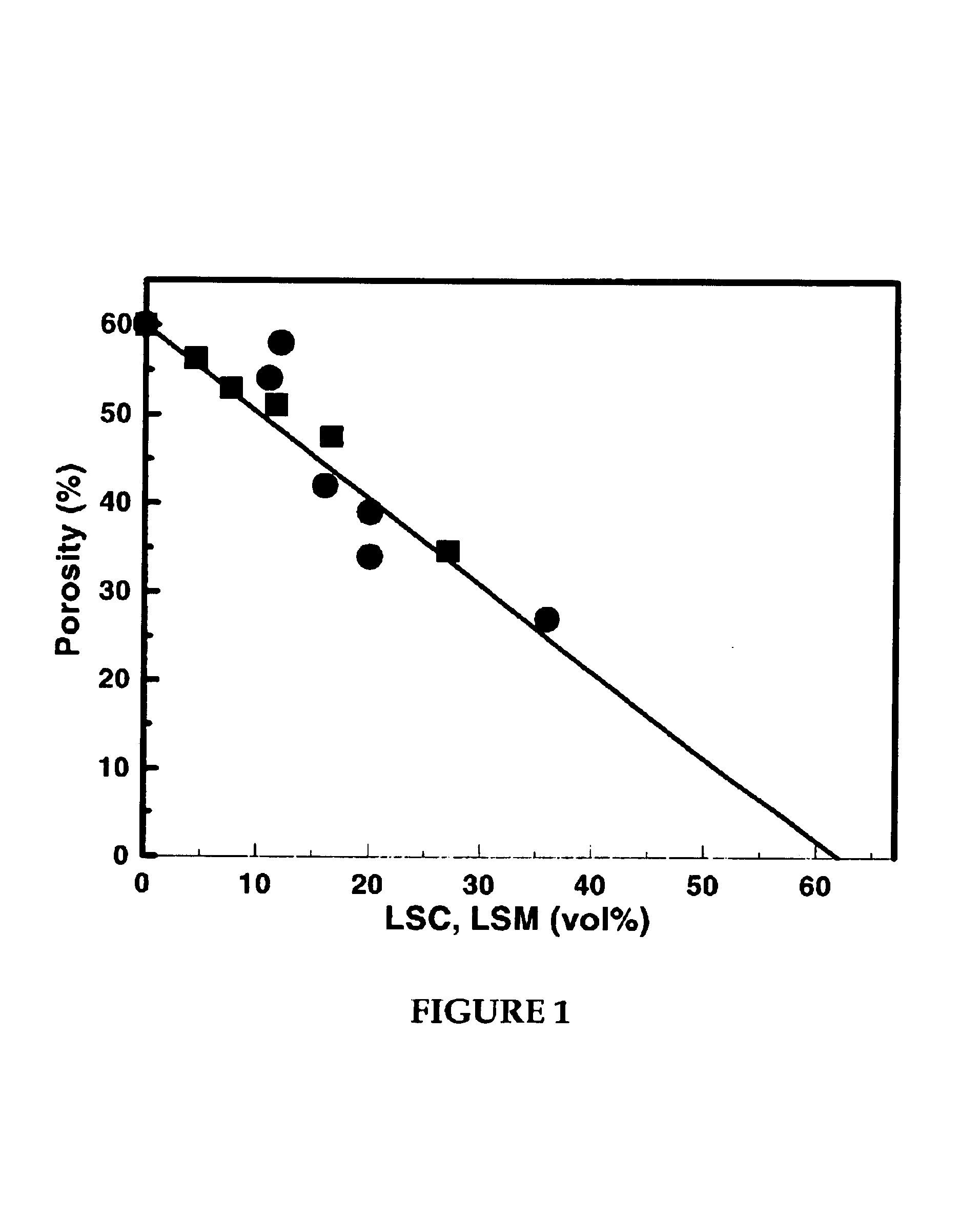
[0065]A series of porous composites were prepared in accordance with Method b above to determine whether the electronically conducting oxide material was being dispersed within the porous matrix. The porosities of a series of materials with increasing amounts of LSM or LSC were measured, with the results shown in FIG. 1. The LSC-YSZ composites in this figure were calcined to 1,100° C. and the LSM-YSZ composites were calcined to 1,250° C. For these data, the volume of the conducting oxide was determined from its mass and bulk density. The line in the figure is the expected change in porosity of the composite assuming the second oxide fills the pores. The fact that the porosity decreases as expected demonstrates that the electronically conducting oxide material is present in the pore structure following the calcination treatments.

[0066]As shown in FIG. 1, the porosity of the LSC-YSZ composite decreases from 60% by volume (e.g., porosity of YSZ matrix) at 0% LSC, to 0% at about 64% by ...

example 2

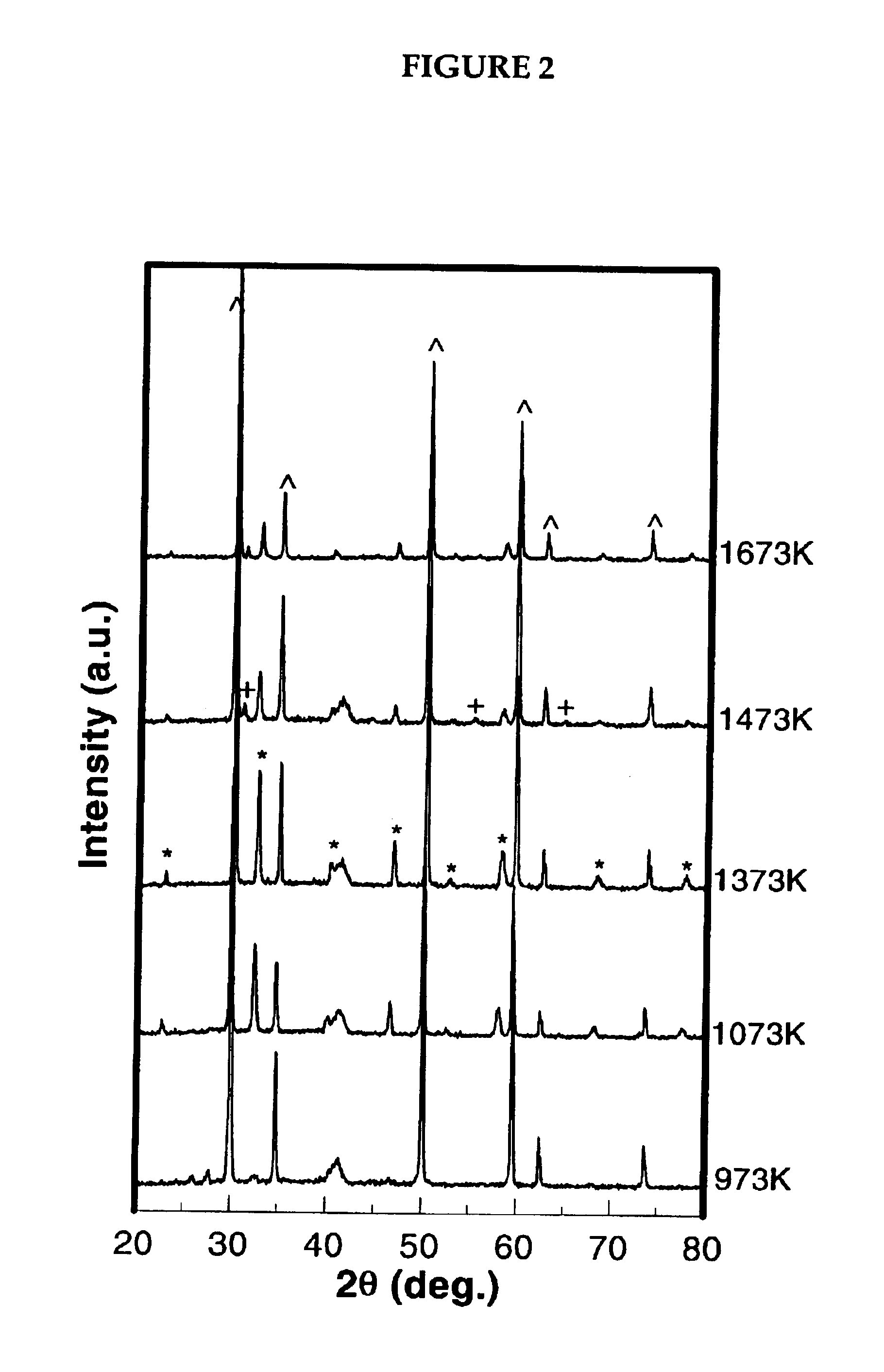
[0067]LSC-YSZ composites that preferably can be used as an anode material were prepared in accordance with method b above. To determine the optimum calcination temperature, method b was repeated at different temperatures, the results of which are shown in FIG. 2. FIG. 2 shows the XRD patterns following impregnation of the porous YSZ with the La, Sr, and Cr salts to a loading that would correspond to about 30 vol wt % LSC, after calcining to increasingly higher temperatures. Peaks corresponding to the LSC, perovskite phase (notably, those at 41, 46, 58, 68, and 78 degrees 2θ) become apparent beginning at approximately 800° C. These peaks become sharper after calcination to 1,100° C., but new phases appear at still higher calcination temperatures. By 1,200° C., a peak appears at 31 degrees, which is believed to be attributed to the formation of SrZrO3. For calcination temperatures below 1,400° C., there are also several overlapping peaks in the region near 41 degrees, which are probab...

example 3

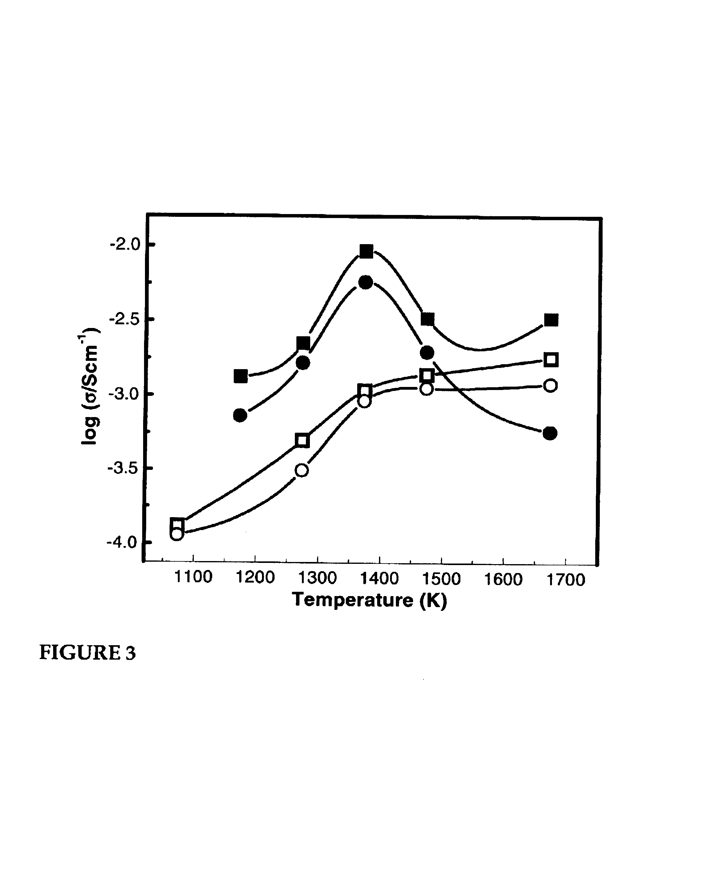
[0068]The purpose of this example was to study the effect of calcination temperature on the electronic conductivity of the composite, the results of which are shown in FIG. 3. Two LSC-YSZ composites were prepared, both having 30 vol % LSC, but one prepared using method a and the other prepared using method b described above. The samples were calcined in air for 2 hours at various temperatures before measuring the conductivities 700° C. in both air and humidified H2. For the composite prepared in accordance with method b, the conductivity was found to increase with temperature to a maximum value at or about 1,100° C., and then to decrease at still higher calcination temperatures. This is consistent with the formation of an LSC phase at 1,100° C., followed by formation of secondary phases at higher temperatures. It also is interesting that the conductivity of the composite formed at the highest temperature is sensitive to the gas-phase composition, while the composite formed at 1,100°...


PUM

PropertyMeasurementUnit
pore sizeaaaaaaaaaa
pore sizeaaaaaaaaaa
pore sizeaaaaaaaaaa

Abstract

The present invention generally relates to porous electrodes for use in solid oxide fuel cells, whereby the electrodes are comprised primarily of ceramic material and electronically conductive material. The electrodes are prepared by impregnating a porous ceramic material with precursors to the electronically conducting material.

Description

FIELD OF THE INVENTION[0001]The present invention relates generally to solid oxide fuel cells (SOFC) and to methods of their preparation. Specifically, the invention relates to porous electrodes and to methods of producing them whereby the electrodes are prepared from a porous matrix impregnated with an electron-conducting material to form a porous electrode. The electrodes can be prepared at temperatures low enough to avoid solid state reactions between, for example, the oxides used to form the matrix and oxides of the electron-conducting material.DESCRIPTION OF THE RELATED ART[0002]Solid oxide fuel cells have grown in recognition as a viable high temperature fuel cell technology. There is no liquid electrolyte, which eliminates metal corrosion and electrolyte management problems typically associated with the use of liquid electrolytes. Rather, the electrolyte of the cells is made primarily from solid ceramic materials that are capable of surviving the high temperature environment ...

Claims


Application Information

Patent Timeline
Patent Type & Authority Patents(United States)
IPC IPC(8): H01M4/88H01M4/90H01M8/12H01M4/86H01M8/24
CPCH01M4/8652H01M4/9033H01M4/9066H01M8/1253H01M2004/8689H01M2008/1293Y02E60/521Y02E60/525Y02E60/50Y02P70/50H01M4/86H01M8/12
Inventor GORTE, RAYMOND J.VOHS, JOHN M.
Owner THE TRUSTEES OF THE UNIV OF PENNSYLVANIA
Why Eureka
Try Eureka