Capacitance type sensor and method for manufacturing same

a technology of capacitive type and sensor, which is applied in the direction of stringed rackets, instruments, force/torque/work measurement apparatus, etc., can solve the problems of wasting power, difficulty in realizing the reduction of consumption power, and inability to properly cancel sleep mode, etc., to achieve the effect of reducing power consumption

Inactive Publication Date: 2005-10-25
NITTA CORP
View PDF5 Cites 85 Cited by
  • Summary
  • Abstract
  • Description
  • Claims
  • Application Information

AI Technical Summary

Benefits of technology

[0015]It is an object of the present invention to provide a capacitance type sensor capable of reducing power consumption by switching to a sleep mode when used with a microcomputer control system.
[0016]Another object of the invention is to provide a capacitance type sensor capable of reducing the hysteresis on the output signal.

Problems solved by technology

This results in wasteful consumption of power.
Unless the output signal changes beyond the threshold voltage, it is impossible to securely detect an operation to the operation button 730 even when monitoring the output signal of the capacitance type sensor 701, resulting in a problem that the sleep mode is not to be properly canceled.
Namely, there is a fear for the capacitance type sensor 701 not to properly effect a switching between the sleep mode and the usual mode, making it difficult to realize the reduction of consumption power.
Such deviation disadvantageously emerges as hysteresis on the output signal or the sensor.
However, it is not suited for the utilization as a device having a switch function for changing-over between different two states (e.g. on-state and off-state).
Thus, a comparatively troublesome process is needed.
Such a troublesome process is similarly required for the conventional other capacitance type sensors, besides the foregoing capacitance type sensor 701.

Method used


Image

  • Capacitance type sensor and method for manufacturing same
  • Capacitance type sensor and method for manufacturing same
  • Capacitance type sensor and method for manufacturing same

Examples


first embodiment

[0095]Now explanation is made on the structure of a capacitance type sensor 1 according to the present invention, with reference to FIGS. 1 to 3.

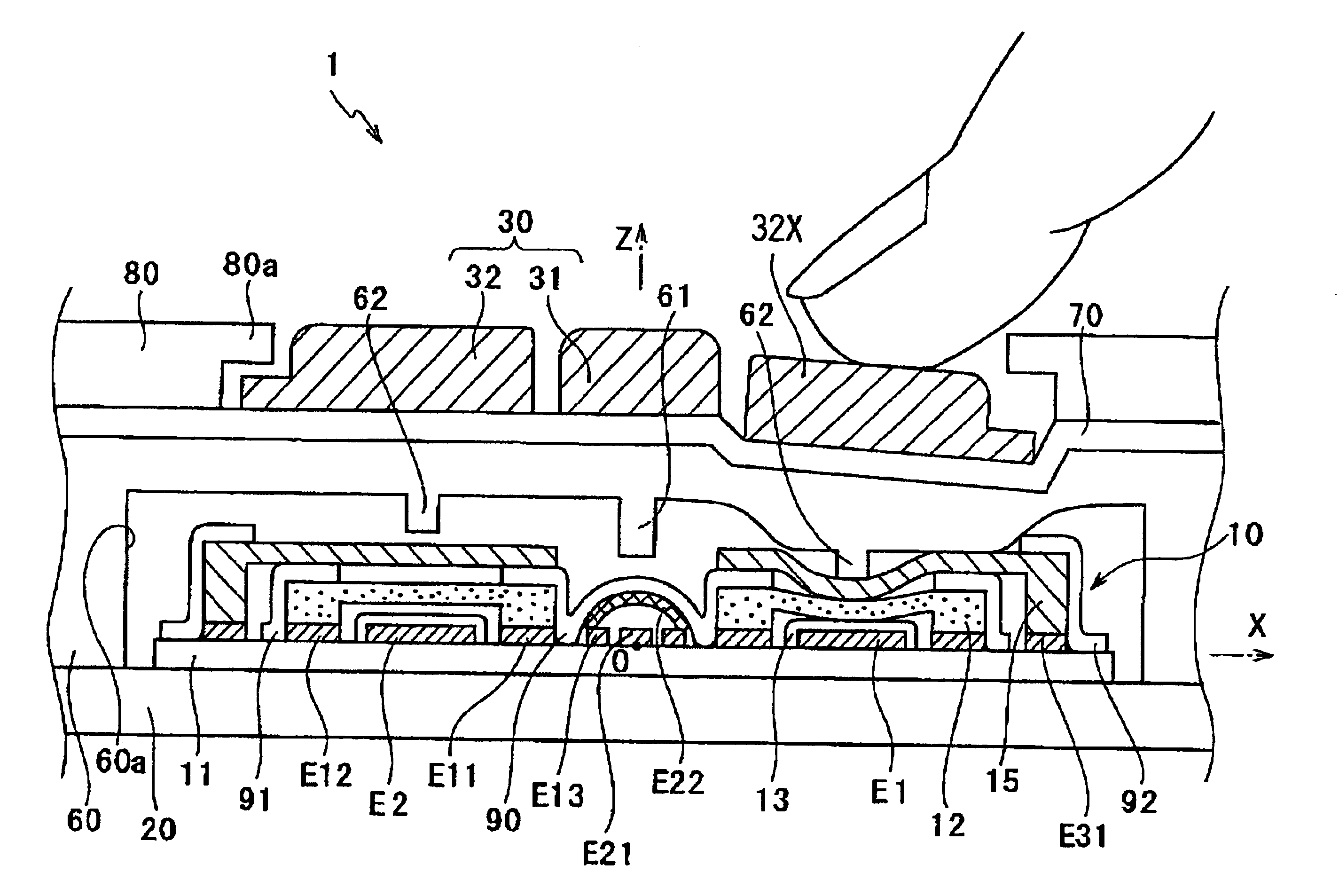
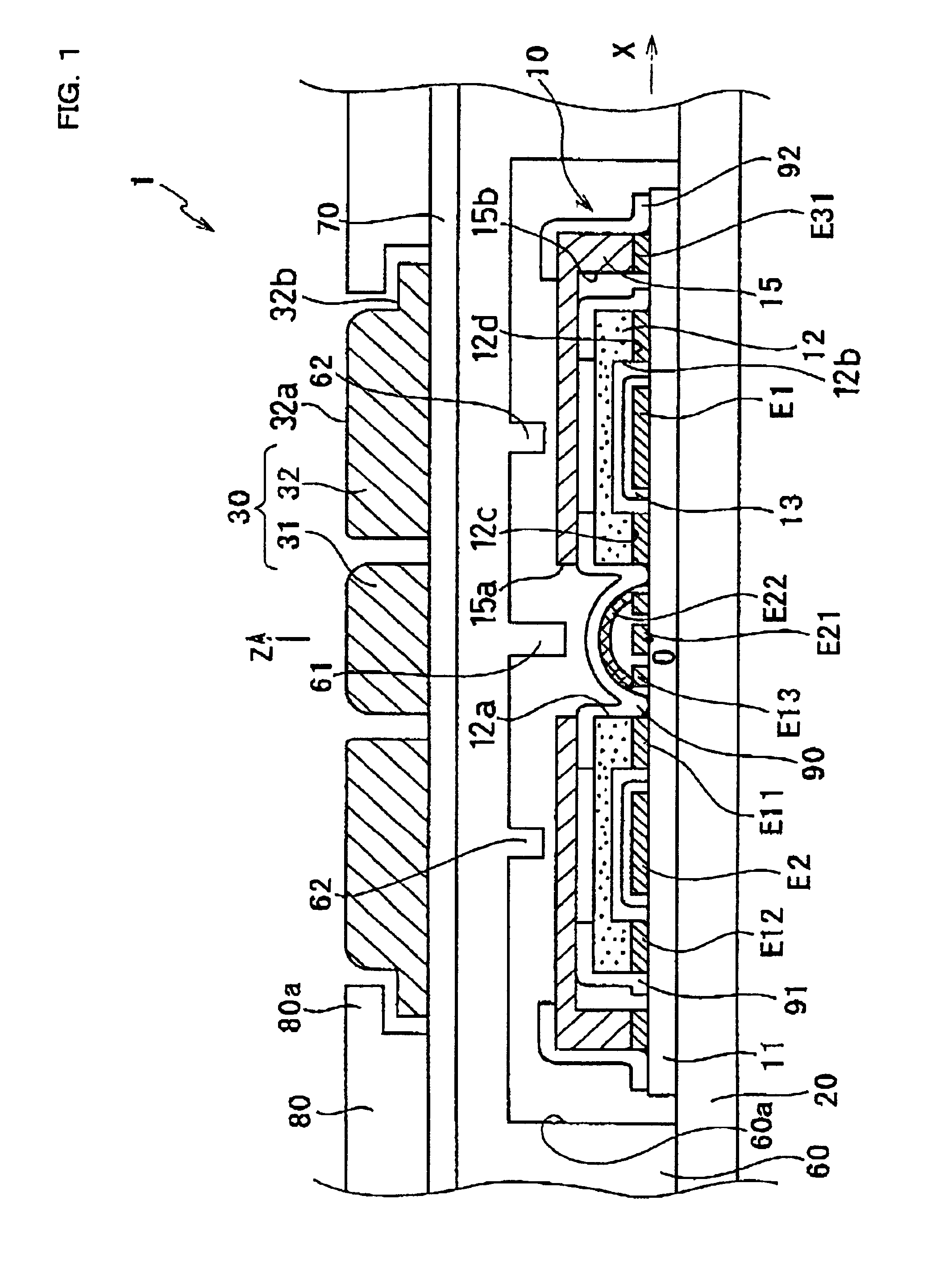
[0096]FIG. 1 is a cross-sectional view of the capacitance type sensor 1 according to the present embodiment. The capacitance type sensor 1 includes a substrate 20, a detection button 30 for detecting a force externally applied, a supporting member 60 fixingly supporting the detection button 30 on the substrate 20, a resin sheet 70 disposed between the detection button 30 and the supporting member 60, a sensor unit 10 arranged between a recess 60a formed generally rectangular in an underside of the supporting member 60 and the substrate 20, and a cover case 80 formed for example of a resin covering around the detection button 30 on an upper surface of the resin sheet 70.

[0097]The substrate 20 is a usual printed circuit substrate for an electronic circuit, which in this embodiment employs a glass epoxy substrate. The substrate 20 may use a fi...

second embodiment

[0177]Now explanation is made on the structure of the capacitance type sensor 201 according to the invention with reference to FIGS. 17 to 19.

[0178]FIG. 17 is a cross-sectional view of a capacitance type sensor according to this embodiment, being shown correspondingly to the first embodiment of FIG. 1. The difference in structure of the capacitance type sensor 201 of this embodiment from the capacitance type sensor 1 of the first embodiment of FIG. 1 lies in the following. Namely, the sensor unit 10 of the first embodiment has one return-switch movable electrode 15 whereas the sensor unit 210 of this embodiment has two return-switch movable electrodes E215, E216. Furthermore, the return-switch movable electrode 15 of the first embodiment is connected with the return-switch fixed electrode E31 whereas the two return-switch movable electrodes E215, E216 of this embodiment are respectively connected with separate return-switch fixed electrodes E231, E232. The other structure is nearly ...

third embodiment

[0210]Now explanation is made on a capacitance type sensor according to the invention, with reference to FIGS. 22, 23A, 23B and 24. FIG. 22 is an external perspective view of a capacitance type sensor 301 according to this embodiment, FIG. 23A is a cross-sectional view on line V—V of the capacitance type sensor 301 of FIG. 22, and FIG. 23B is an arrangement view showing the electrodes on a substrate of the capacitance type sensor 301 of FIG. 22. FIG. 24 is a circuit diagram showing an equivalent circuit concerning the capacitance type sensor 301 of FIG. 22.

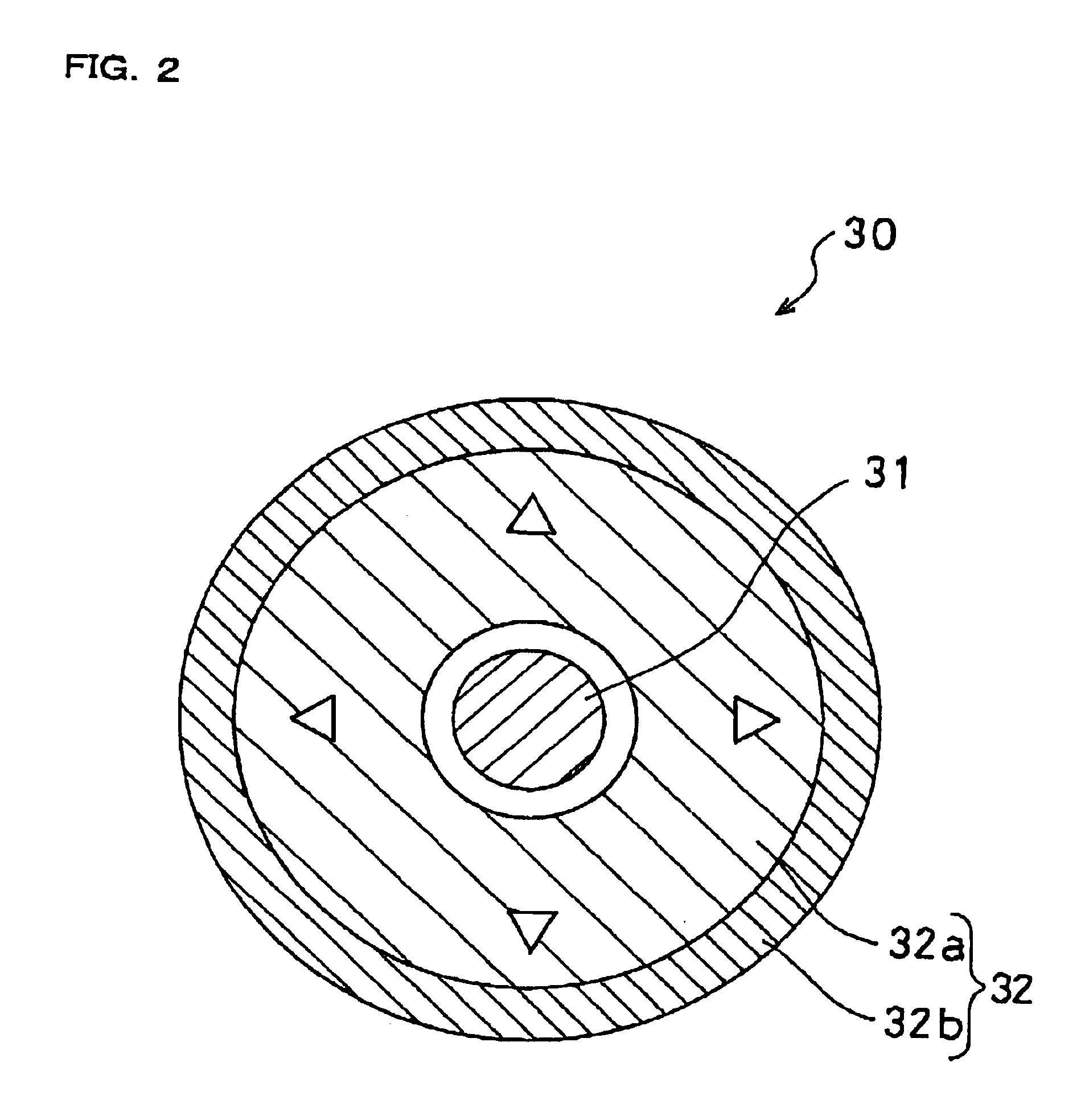
[0211]Although the detection button 30 of the foregoing first and second embodiments is configured by a plurality of members, i.e., central button 31 and direction button 32, the detection button 330 in this embodiment is configured by a single member as suitably shown in FIG. 23A. The detection button 330 of this embodiment is accommodated, for play-fit, within a hollow housing of cover case 380, e.g., of resin. This has a projec...


PUM

PropertyMeasurementUnit
capacitanceaaaaaaaaaa
distanceaaaaaaaaaa
tensile forceaaaaaaaaaa

Abstract

In a capacitance type sensor of the present invention, a capacitance element is constituted between a displacement electrode and a capacitance element electrode. A return-switch movable electrode is arranged above and spaced from the displacement electrode, to be placed in contact with the displaying electrode due to a displacement of a direction button. When the direction button is operated, the return-switch movable electrode is first displaced into contact with the displacement electrode. Then, the both make a displacement while keeping a contact state. When the displacement electrode is displaced to change the spacing to the capacitance element electrode, changed is the capacitance value of the capacitance element. Based on this change, a force is recognized. Herein, in the course of a transit from a state the displacement electrode and the return-switch electrode are not in contact to a state of their contact, the output signal varies necessarily beyond a threshold voltage.

Description

CROSS-REFERENCE TO RELATED APPLICATIONS[0001]This application is based upon and claims priority of Japanese Patent Application Nos.: (1) 2002-155251 filed on May 29, 2002; (2) 2002-301709 filed on Oct. 16, 2002; and (3) 2003-127980 filed on May 6, 2003.BACKGROUND OF THE INVENTION[0002]1. Field of the Invention[0003]The present invention relates to a capacitance type sensor suited for use in detecting a force and to a method for manufacturing same.[0004]2. Description of Related Art[0005]The capacitance type sensor generally is used as a device for detecting a force by converting a magnitude and direction of a force applied by an operator into an electric signal. Particularly, the recent utilization is as a two-dimensional or three-dimensional sensor that can detect an applied force on a directional-component basis. For example, there is an input device of cellular phone incorporating, as what is called a joystick, a capacitance type sensor to input the operation in multi-dimensional...

Claims


Application Information

Patent Timeline
Patent Type & Authority Patents(United States)
IPC IPC(8): G01L5/22G01L5/16G01L9/00G01L1/14G06F1/32G06F3/033G06F3/044H01H25/04
CPCG01L1/142G01L5/165G01L5/223G01L9/0072G06F1/3215G06F3/044H01H25/041G01L1/144Y10T29/49103H01H2025/048H01H2239/006H01H2300/022Y10T29/49005Y10T29/4902Y10T29/49002
Inventor MORIMOTO, HIDEO
Owner NITTA CORP
Why Eureka
Try Eureka