Laser scanning unit

a laser scanning and laser technology, applied in the field of laser scanning units, can solve the problems of difficult use of the plurality of light sources, affecting the optical performance of the laser scanning unit, and errors in linearity, so as to prevent the change of focal distance, maintain optical performance, and correct linearity errors.

Inactive Publication Date: 2005-10-25
SAMSUNG ELECTRONICS CO LTD
View PDF4 Cites 0 Cited by
  • Summary
  • Abstract
  • Description
  • Claims
  • Application Information

AI Technical Summary

Benefits of technology

[0010]The present invention provides a laser scanning unit (LSU) that corrects linearity errors when projecting a plurality of laser light beams onto a polygon mirror, prevents focal distance changes due to a temperature shifts, and maintains optical performance.

Problems solved by technology

Because of the different incident angles, errors in linearity can occur.
It is difficult to use the plurality of light sources, however, to project the light beams emitted from each light source onto the polygon mirror with the same incidence angle without a loss of luminous intensity.
In addition, changes in focal distances that result from temperature shifts generally affects the optical performance of the LSU.

Method used


Image

  • Laser scanning unit
  • Laser scanning unit
  • Laser scanning unit

Examples


Embodiment Construction

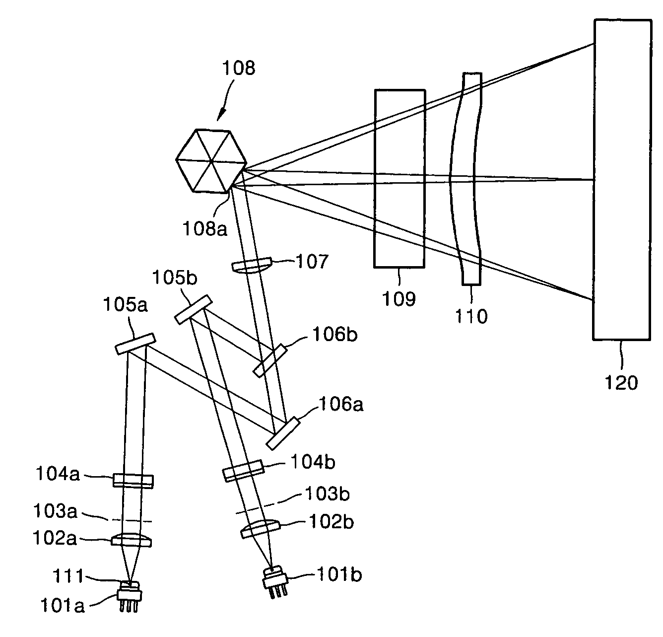
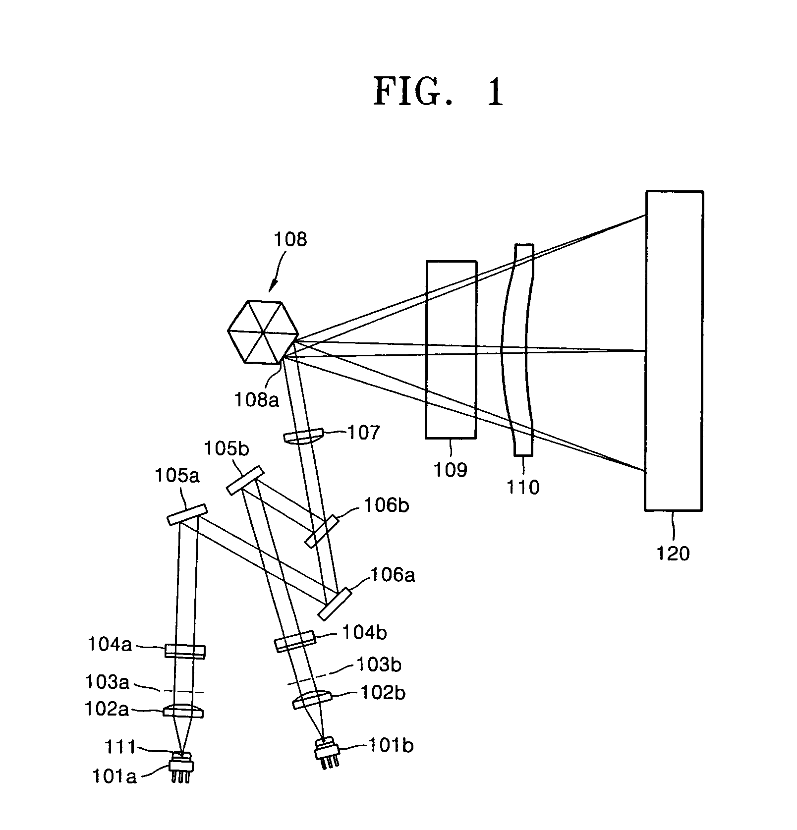
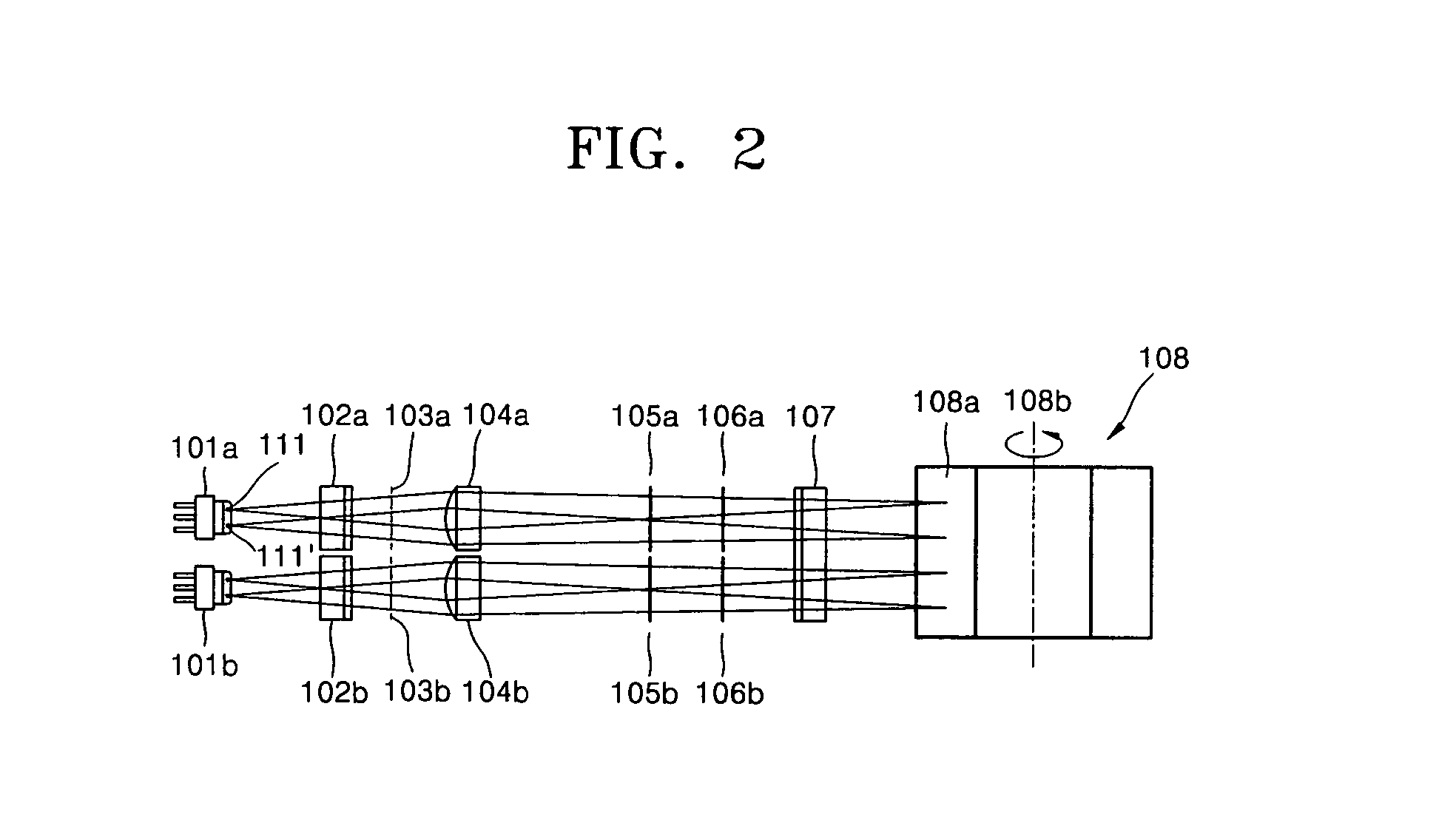
[0017]FIG. 1 is a plane view schematically illustrating the structure of a laser scanning unit (LSU) according to an embodiment of the present invention. FIG. 2 is a drawing illustrating proceeding sub-scanning directions of light beams from light sources to a polygon mirror in the LSU of FIG. 1. FIG. 3 is a perspective view illustrating a first cylinder lens of FIG. 1. FIG. 4 is a perspective view illustrating a second cylinder lens of FIG. 1. Each light source has at least one light-emitting point.

[0018]Referring to FIGS. 1 through 4, the LSU includes a plurality of light sources 101a and 101b, a polygon mirror 108 reflecting a plurality of light beams respectively emitted by the light sources 101a and 101b, first cylinder lenses 104a and 104b and a second cylinder lens 107 that converges or directly transmits the light beams emitted from the light sources 101a and 101b. The first cylinder lenses 104a and 104b are disposed along proceeding paths of the light beams between the ligh...


PUM


Abstract

A laser scanning unit is provided comprising a polygon mirror that deflects light beams respectively emitted by a plurality of light sources, an image focusing system that respectively focuses an image corresponding to each light beam deflected from the polygon mirror onto a surface of a plurality of photoconductive drums, and an incident optical system disposed between the light sources and the polygon mirror. The incident optical system comprises an infinite optical system along a main scanning direction and a finite optical system along a sub-scanning direction.

Description

PRIORITY[0001]This application claims priority of Korean Patent Application No. 2003-32254, filed on May 21, 2003, in the Korean Intellectual Property Office, the entire contents of which are incorporated herein by reference.BACKGROUND OF THE INVENTION[0002]1. Field of the Invention[0003]The present invention relates to a laser scanning unit for an image forming device, and more particularly, to a tandem type laser scanning unit that scans a plurality of light sources over one deflecting device and projects images on a plurality of photoconductive drums.[0004]2. Description of the Related Art[0005]In general, a laser scanning unit (LSU) is used in image forming devices such as copiers, printers, or facsimile machines, all of which print images on printing paper. The LSU scans a light beam emitted from a light source, for example, a laser diode, to a photoconductive medium of the image forming device and makes an electrostatic latent image.[0006]Laser scanning units can be described ...

Claims


Application Information

Patent Timeline
Patent Type & Authority Patents(United States)
IPC IPC(8): G02B26/12B41J2/44G02B26/10G03G15/04H04N1/113
CPCG02B26/123G03G15/04
Inventor KIM, HYUNG-SOO
Owner SAMSUNG ELECTRONICS CO LTD
Why Eureka
Try Eureka