Disk drive control system having a servo processing accelerator circuit

a technology of accelerator circuit and disk drive, which is applied in the direction of magnetic recording, data recording, instruments, etc., can solve problems such as affecting the ability of the internal microprocessor of the disk driv

Inactive Publication Date: 2005-10-25
WESTERN DIGITAL TECH INC
View PDF9 Cites 116 Cited by
  • Summary
  • Abstract
  • Description
  • Claims
  • Application Information

AI Technical Summary

Benefits of technology

[0007]In more detailed features of the invention, the control system may further include a bus for transmitting the WUS limit parameter from the microprocessor to the accelerator circuit. The accelerator circuit further comprises a WUS limit register for storing the WUS limit parameter and/or a PES register for storing the calculated PES value. The PES value may be further based on a parameter stored in a parameter register. The servo processing accelerator circuit may have a plurality of multipliers that may simultaneously perform parallel calculations.
[0008]Alternatively, the present invention may be embodied in a control system for processing data from sampled servo wedges for positioning a transducer head in a disk drive. In this embodiment, the servo processing accelerator circuit includes a position error signal (PES) calculator circuit for calculating a stream of PES values based on data read from the sampled servo wedges, and a servo-loop compensator for processing the stream of PES values and generating a stream of control effort values for positioning the transducer head during a track following operation.
[0009]Another embodiment of the invention may reside in a magnetic disk drive having a head disk assembly (HDA) and a control system. The HDA includes a rotating magnetic disk having distributed position information in a plurality of uniformly spaced-apart servo wedges for defining data storage tracks, an actuator for positioning a transducer head in response to a control effort signal, and the transducer head for periodically reading the distributed position information from the servo wedges and reading data from the data storage tracks. The control system has an accelerator circuit for implementing a first sampled servo controller, and has a second sampled servo controller separate from the accelerator circuit. The first sampled servo controller periodically adjusts the control effort signal based on the distributed position information only during a track-following operation under one or more of a first set of predetermined conditions. The first sampled servo controller also indicates the occurrence of a predetermined condition within a second set of predetermined conditions to the control system. The second sampled servo controller periodically adjusts the control effort signal based on the distributed position information during a track-following operation under one or more of a second set of predetermined conditions. The control system selects the first sampled servo controller for adjusting the control effort signal during a track-following operation under one or more of a first set of predetermined conditions, and selects the second sampled servo controller for adjusting the control effort signal du...

Problems solved by technology

Unfortunately, processing the additional servo wedges, depending on the task loading, may impact the abil...

Method used


Image

  • Disk drive control system having a servo processing accelerator circuit
  • Disk drive control system having a servo processing accelerator circuit
  • Disk drive control system having a servo processing accelerator circuit

Examples


first embodiment

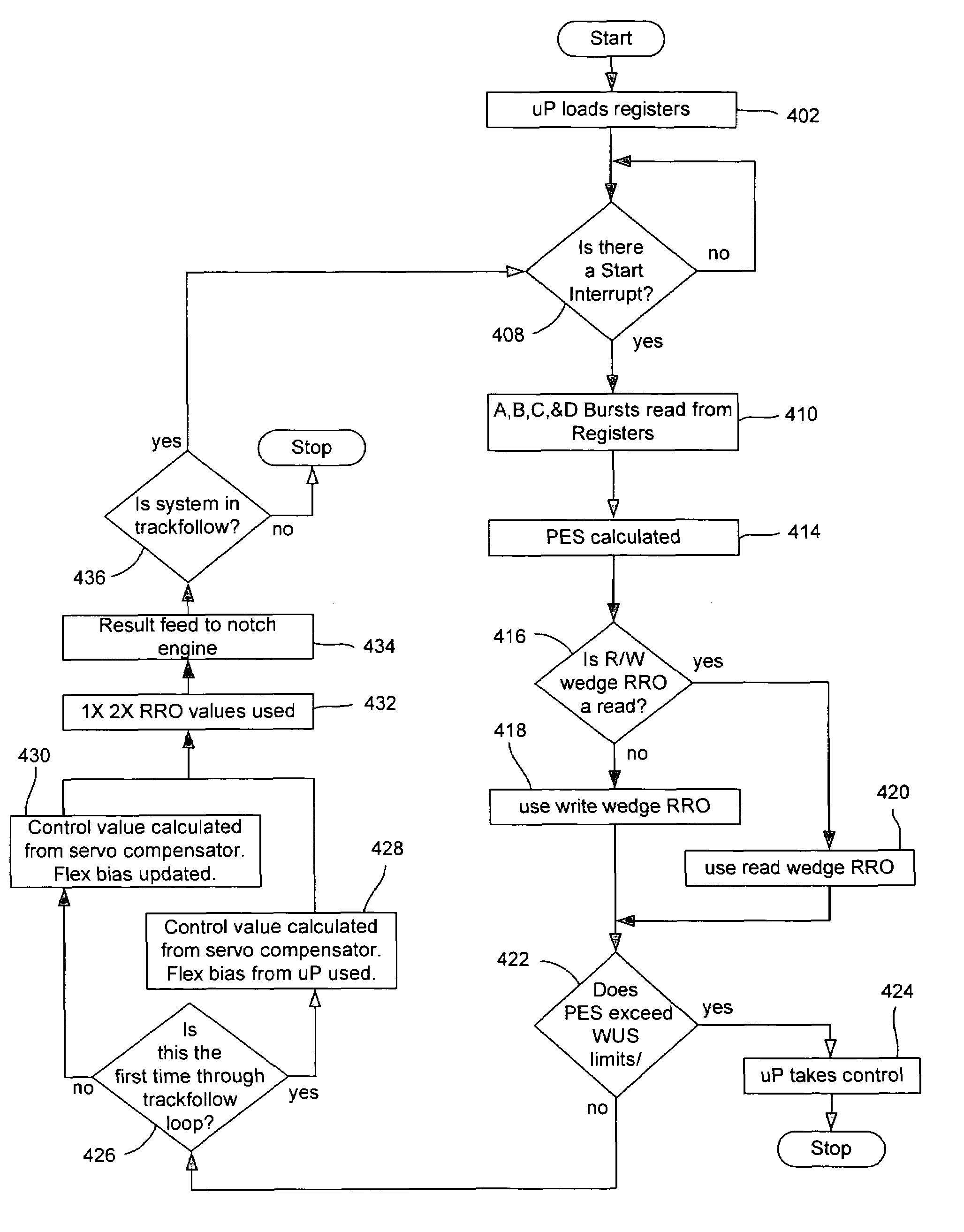
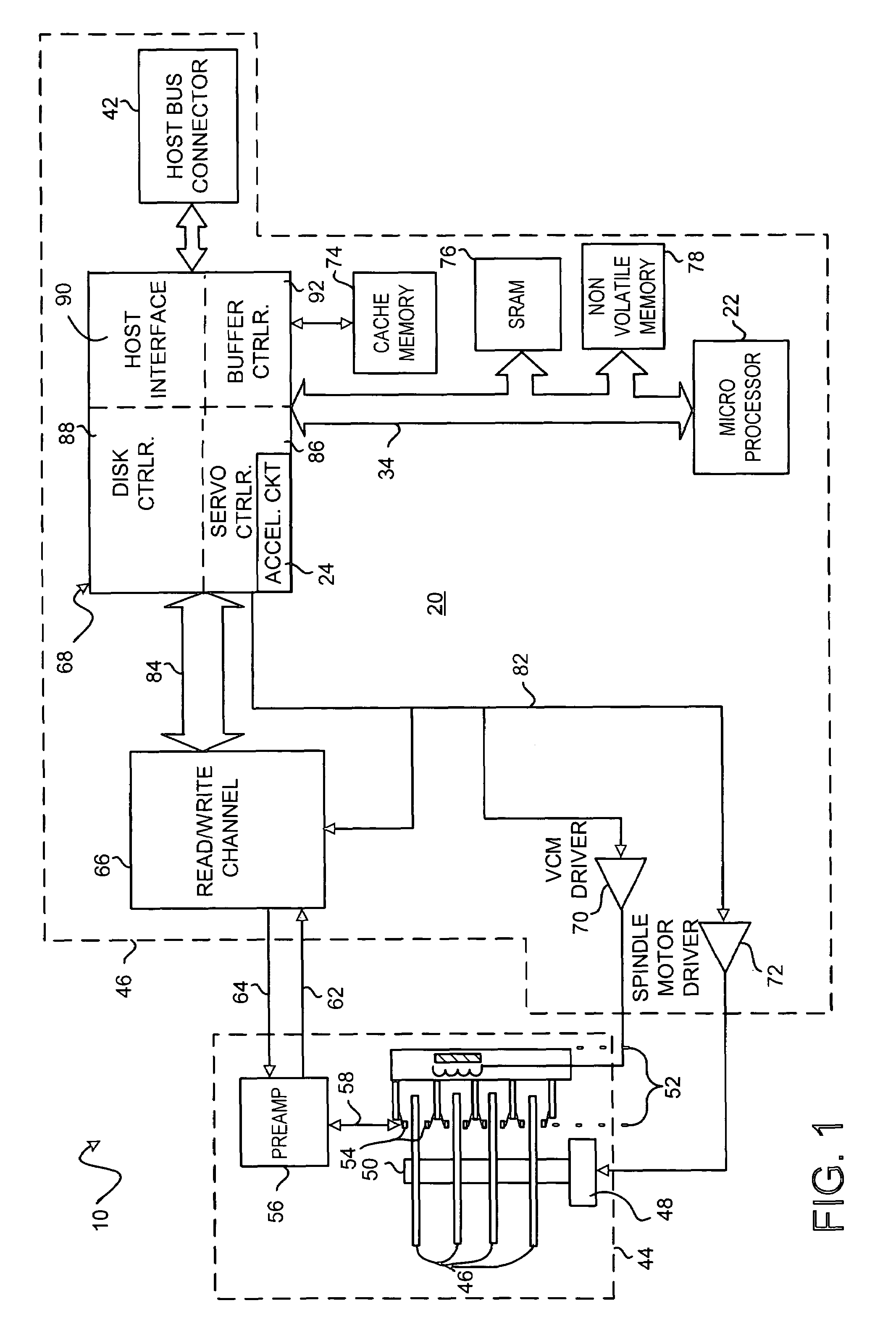
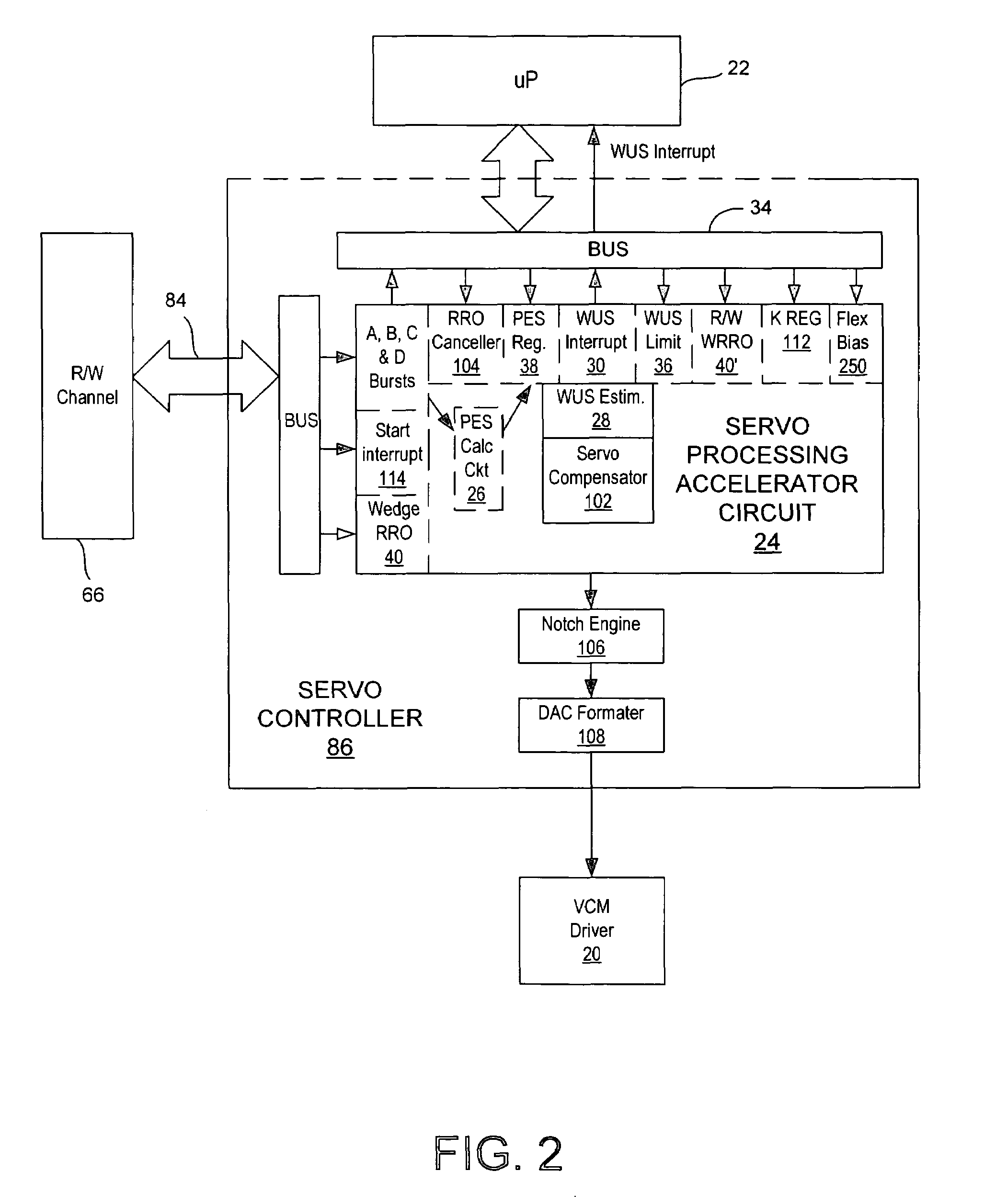
[0024]With reference to FIGS. 1 and 2, the present invention may reside in a control system 20 for processing sampled servo data in a disk drive 10. The control system includes a microprocessor 22 for executing firmware code, and a servo processing accelerator circuit 24 for performing operations on the sampled servo data while the microprocessor is executing the firmware code. The accelerator circuit has a position error signal (PES) calculator circuit 26 for calculating a PES value based on the sampled servo data, and has a write unsafe (WUS) estimator 28 responsive to the calculated PES value and to a WUS limit parameter. The WUS estimator further signals the microprocessor when the calculated PES value exceeds the WUS limit parameter using, e.g., a WUS interrupt 30.

[0025]The control system 20 further includes a bus 34 for transmitting the WUS limit parameter from the microprocessor 22 to the servo processing accelerator circuit 24. The accelerator circuit further comprises a WUS...

second embodiment

[0047]With reference again to FIGS. 1 and 2, the present invention may reside in a control system 20 for processing data from sampled servo wedges for positioning a transducer head 54 in a disk drive 10. In this embodiment, the servo processing accelerator circuit 24 includes a position error signal (PES) calculator circuit 26 for calculating a stream of PES values based on data read from the sampled servo wedges, and a servo-loop compensator 102 for processing the stream of PES values and generating a stream of control effort values for positioning the transducer head during a track following operation.

third embodiment

[0048]the invention may reside in a magnetic disk drive 10 having a head disk assembly (HDA) 44 and a control system 20. The HDA includes a rotating magnetic disk 50 having distributed position information in a plurality of uniformly spaced-apart servo wedges for defining data storage tracks, an actuator 52 for positioning a transducer head 54 in response to a control effort signal, the transducer head for periodically reading the distributed position information from the servo wedges and reading data from the data storage tracks. The control system has an accelerator circuit 24 for implementing a first sampled servo controller, and has a second sampled servo controller (implemented by, e.g., the microprocessor 22) separate from the accelerator circuit. The first sampled servo controller periodically adjusts the control effort signal based on the distributed position information only during a track-following operation under one or more of a first set of predetermined conditions. The...


PUM


Abstract

Disclosed is a control system for processing sampled servo data in a disk drive. The control system includes a microprocessor and a servo processing accelerator circuit for performing operations on the sampled servo data while the microprocessor is executing firmware code. The accelerator circuit supports the use of a higher servo bandwidth thus allowing a higher track density resulting a greater storage capacity for the disk drive. Also, the accelerator circuit relieves the microprocessor of the ordinary servo processing function. Thus, the microprocessor's limited processing capacity to be directed to other controller and interface functions of the disk drive. Only under unusual conditions, such as a write-unsafe (WUS) limit exception, does the microprocessor need to direct processing capacity to the servo processing function. Further, the accelerator circuit may be a decreased response time after reading the servo data from the disk.

Description

BACKGROUND OF THE INVENTION[0001]1. Field of the Invention[0002]The present invention relates to magnetic disk drives, and more particularly, to a disk drive having a servo processing accelerator circuit.[0003]2. Description of the Prior Art and Related Information[0004]Competitive market factors have continually pushed disk drive manufacturers to provide increased data storage capacity while rigidly controlling manufacturing cost. One key to increased storage capacity is increased track density, often expressed as tracks per inch or TPI. Disk drives having a higher TPI generally require a higher servo bandwidth. To support the higher servo bandwidth, more servo wedges are needed on the disk surface. Unfortunately, processing the additional servo wedges, depending on the task loading, may impact the ability of the disk drive's internal microprocessor to perform other tasks of lesser importance in a timely manner.[0005]Accordingly, there exists a need for a increasing the servo bandw...

Claims


Application Information

Patent Timeline
IPC IPC(8): G11B5/596
CPCG11B5/596G11B5/5534G11B5/59627
Inventor CODILIAN, RAFFIELL, TRAVIS E.
Owner WESTERN DIGITAL TECH INC
Why Eureka
Try Eureka