Torque locking system for fastening a wear member to a support structure

a technology of torque locking and wear members, which is applied in the direction of drags, rod connections, manufacturing tools, etc., can solve the problems of eroded teeth, frequent replacement, and dislodged wedges, and achieve the effect of convenient installation and removal

Inactive Publication Date: 2005-11-01
ESCO CANADA
View PDF21 Cites 65 Cited by
  • Summary
  • Abstract
  • Description
  • Claims
  • Application Information

AI Technical Summary

Benefits of technology

[0008]It is therefore an object of the present invention to overcome the disadvantages of the prior art. It is a further object to provide a locking assembly for attaching a wear member to a support structure that is easy to install and remove, does not require the application of any significant force or impact to install or remove, and that remains functional during long periods of use.

Problems solved by technology

These teeth erode through use and are frequently replaced.
This design has the disadvantage that the wedges would often become dislodged during use of the excavating equipment.
However, removal of the wedges became difficult and time consuming.
Further, during removal, the wedges had a tendency to shatter or break causing pieces to jam in the slots and posed a serious safety hazard to workers.
This assembly had the disadvantage of being cumbersome and complex in design making it difficult to use and increasing the time needed to replace the tooth.
As well, the pin has a tendency to loosen from the insert while the tooth is in use.
This assembly suffers from the drawback that the key would often fall out of the passage during use of the tooth allowing the tooth to fall off the adaptor.
It needs to remain functional throughout its service life so that even after a long period of use, it can still easily release a worn-out wear member that is due for replacement.

Method used


Image

  • Torque locking system for fastening a wear member to a support structure
  • Torque locking system for fastening a wear member to a support structure
  • Torque locking system for fastening a wear member to a support structure

Examples


Embodiment Construction

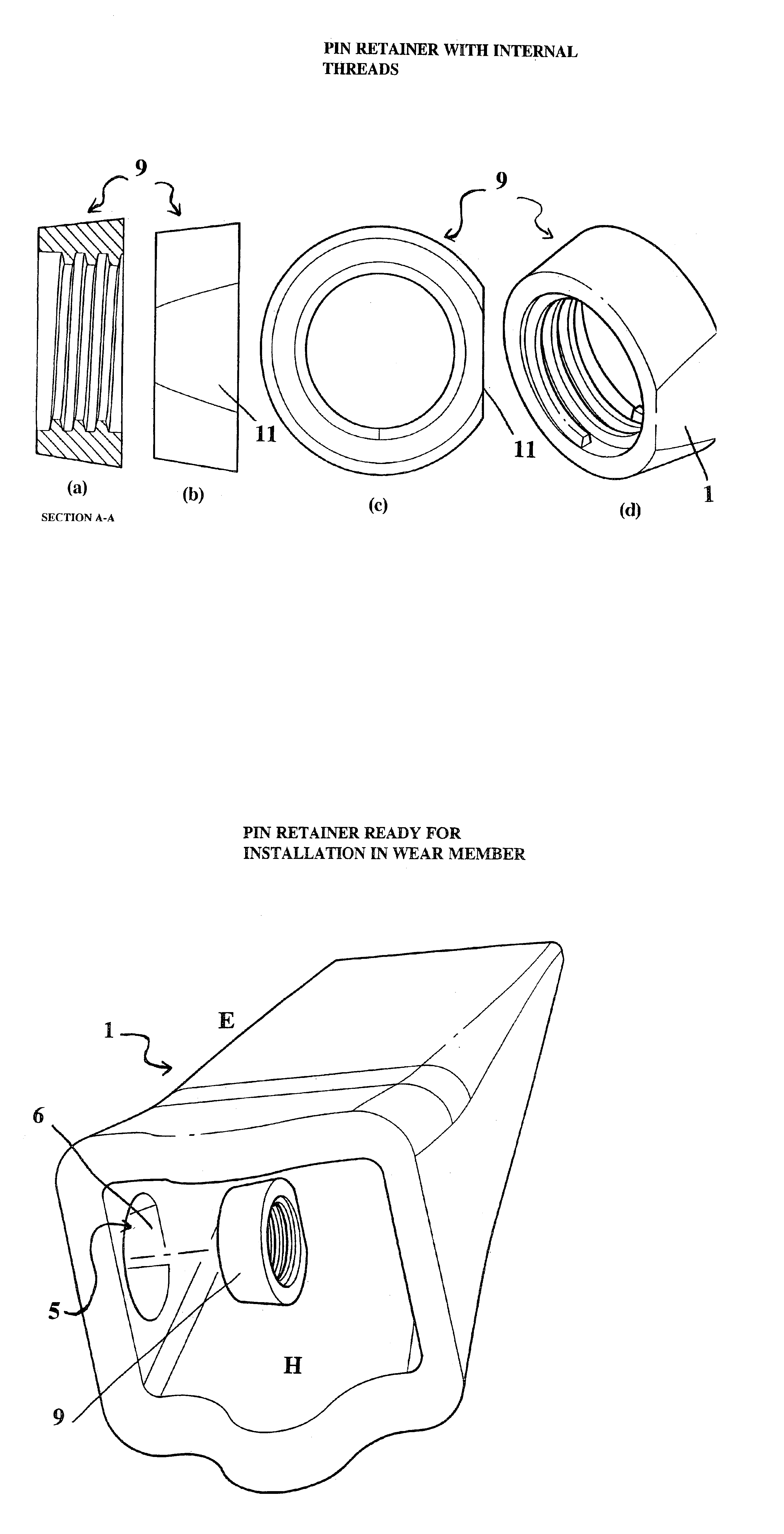
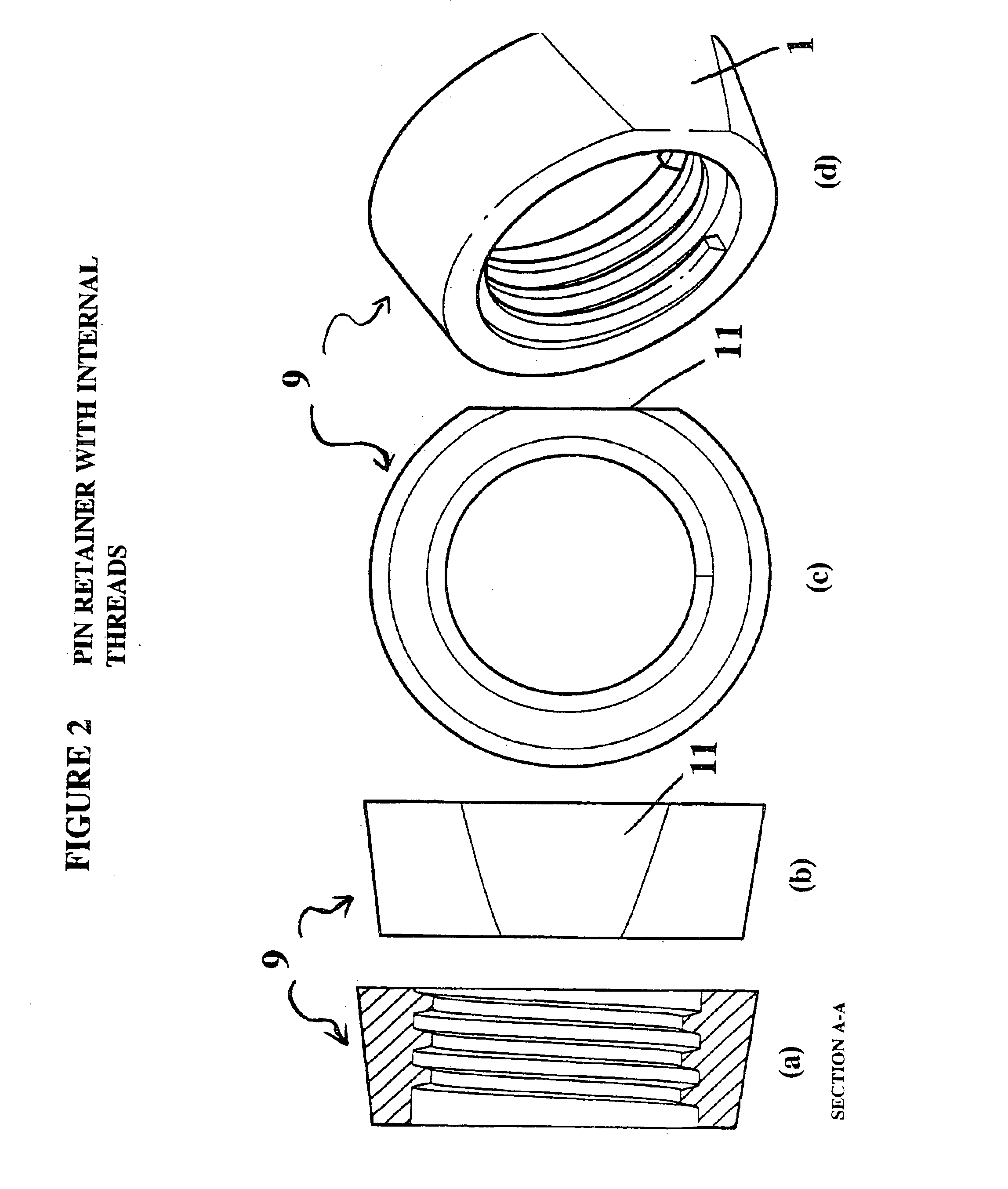
[0023]With reference to the Figures, there is provided an assembly and method for locking a wear member to a support structure. The locking mechanism may be used to lock a tooth to an adaptor, a lip shroud to a bucket lip, or for other analogous uses.

[0024]The assembly comprises a pin retainer and lock pin. The retainer and pin are positioned in a wear member on a support structure having corresponding openings to lock the wear member to the support structure.

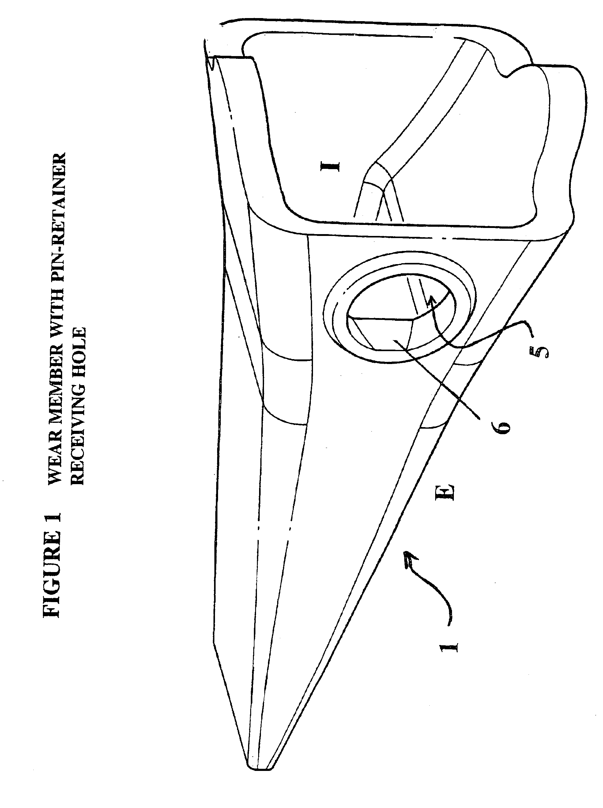
[0025]An excavating tooth or wear member generally has a triangular shaped cross-section and is formed so as to be received over the working end of a support structure. A wear member 1 is shown in FIG. 1 and a support structure 3 in FIG. 4. The wear member has an external surface E and an internal surface I. The wear member has at least one pin-retainer-receiving opening 5 extending through its wall from its external surface E to its internal surface I. This opening 5 is positioned in one side of the wear member 1. The walls of...


PUM


Abstract

The present invention is directed to a releasable locking assembly for attaching a wear member to a support structure. It may be used with excavating equipment for attaching ground-engaging teeth to adaptors, lip shrouds to bucket lips, or other analogous uses. The wear member includes at least one pin-retainer-receiving opening in one side. The opening is tapered, being narrower at its outer surface and wider at its inner surface. The support structure includes at least one pin-receiving recess which generally aligns with the opening in the wear member when the wear member and the support structure are operatively coupled. The pin retainer is a frustoconically shaped cylinder which is threaded internally. It is inserted into the opening in the wear member. The wear member is slidably mounted onto the support structure. The pin is an elongate body which is externally threaded. It is screwed into the pin retainer by the application of torque force from a standard ratchet tool. The pin extends through the wear member and into the recess in the support structure to lock the wear member to the support structure. The pin may be released using a ratchet tool and removed from the pin retainer. The wear member may then be removed from the support structure.

Description

CROSS REFERENCE TO RELATED APPLICATIONS[0001]This application claims priority to Canadian Patent Application No. 2,312,550, filed Jun. 27, 2000 which is incorporated herein by reference.FIELD OF THE INVENTION[0002]The present invention relates to the field of assemblies for fastening wear members to support structures, for example, ground engaging teeth to adaptors of powered equipment.BACKGROUND OF THE INVENTION[0003]Many types of excavating equipment utilize replaceable ground-engaging teeth. These teeth erode through use and are frequently replaced. Depending on the conditions, a given support structure or adaptor would be re-equipped with from 5 to 30 teeth to maintain a sharp penetrating edge during excavation. The ease of replacement of the teeth is important because it minimizes the amount of wasted throw-away material and also minimizes the downtime of the tool.[0004]The prior art assemblies used to attach a tooth to the adaptor consist mainly of two designs, the wedge desig...

Claims


Application Information

Patent Timeline
Patent Type & Authority Patents(United States)
IPC IPC(8): E02F9/28
CPCE02F9/2825E02F9/2833Y10T403/7067
Inventor ADAMIC, DWIGHT L.SMITH, MURRAY
Owner ESCO CANADA
Why Eureka
Try Eureka