
Method and device for improving stacker conveyor speed in a mail stacker

a technology of mail stacker and conveyor, which is applied in the direction of transportation and packaging, thin material handling, article delivery, etc., can solve the problems of too light pack pressure, inability to squeeze new mailpieces into the stack, and too tightly packed mailpieces

Active Publication Date: 2005-11-01
DMT SOLUTIONS GLOBAL CORP
View PDF5 Cites 7 Cited by
  • Summary
  • Abstract
  • Description
  • Claims
  • Application Information

AI Technical Summary

Benefits of technology

[0010]It is advantageous and desirable to provide a method and system to control the movement of the conveyor belt so that the pressure in a mail stack can be properly maintained.

Problems solved by technology

This step in the mass mailing process has been found to be a “bottleneck”.
If the conveyor belt moves too slowly, the mailpieces will be packed too tightly.
After a short time, a new mailpiece will not be able to squeeze into the stack and it will jam.
If the conveyor belt moves too fast, the pack pressure will be too light and the mailpieces will move around as they settle down.
In that situation, if an incoming mailpiece hits one of the mailpieces in the stack that is out of position, a jam may occur.
Moreover, if the pack pressure is too light, the operator has to clear the stack more frequently.
This makes the stacker less effective.
For example, when the mail stacker is first turned on, the motor that drives the conveyor belt is cold.
Manual adjustment, however, is not always consistent.
One of the major pressure-related problems is caused by the variation of the thickness of the mailpieces.
If the speed of the conveyor belt is set for thin mailpieces, then this speed will not work well for thick mailpieces, because the stack pressure will rapidly increase, thus quickly causing a full jam.
Even if a full jam does not occur, the late arriving mailpieces may not be stacked properly.
As such, the edge of the mail stack will not form a straight line, causing a problem for the operator when the mail stack has one or more zip-code breaks.
When the stack pressure is too high, however, the mailpieces may not be properly stacked to indicate the zip-code break.

Method used


Image

  • Method and device for improving stacker conveyor speed in a mail stacker
  • Method and device for improving stacker conveyor speed in a mail stacker
  • Method and device for improving stacker conveyor speed in a mail stacker

Examples


Embodiment Construction

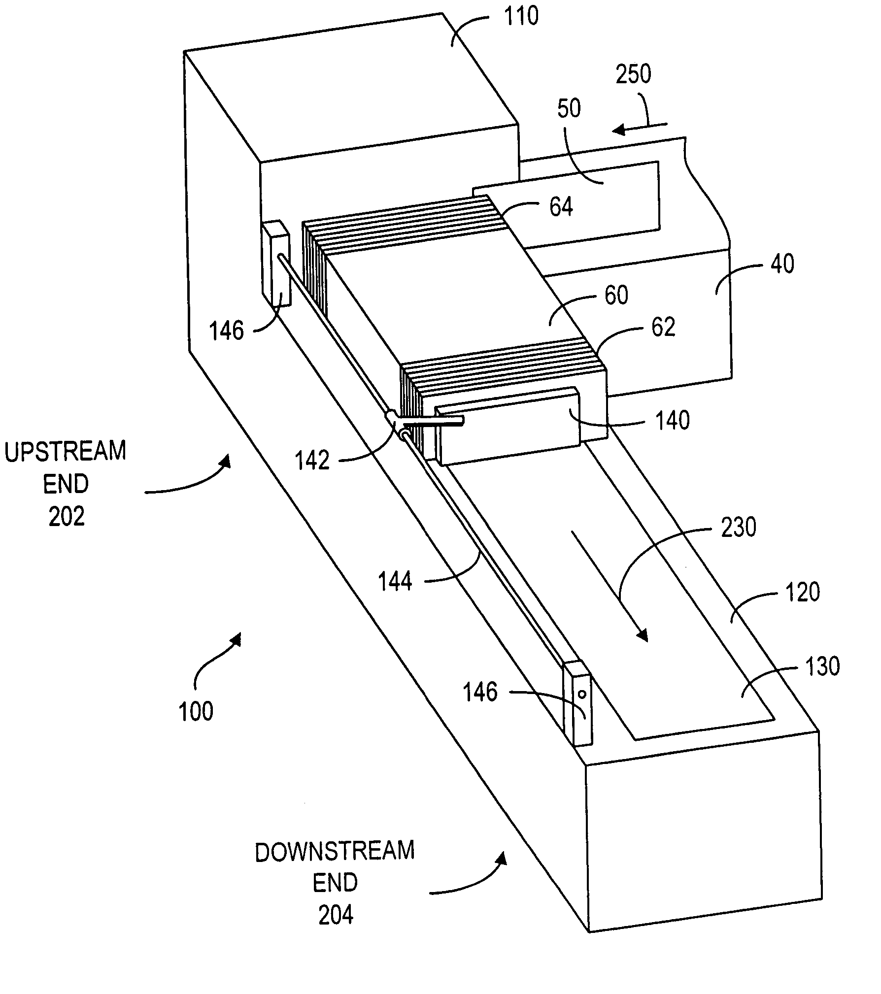
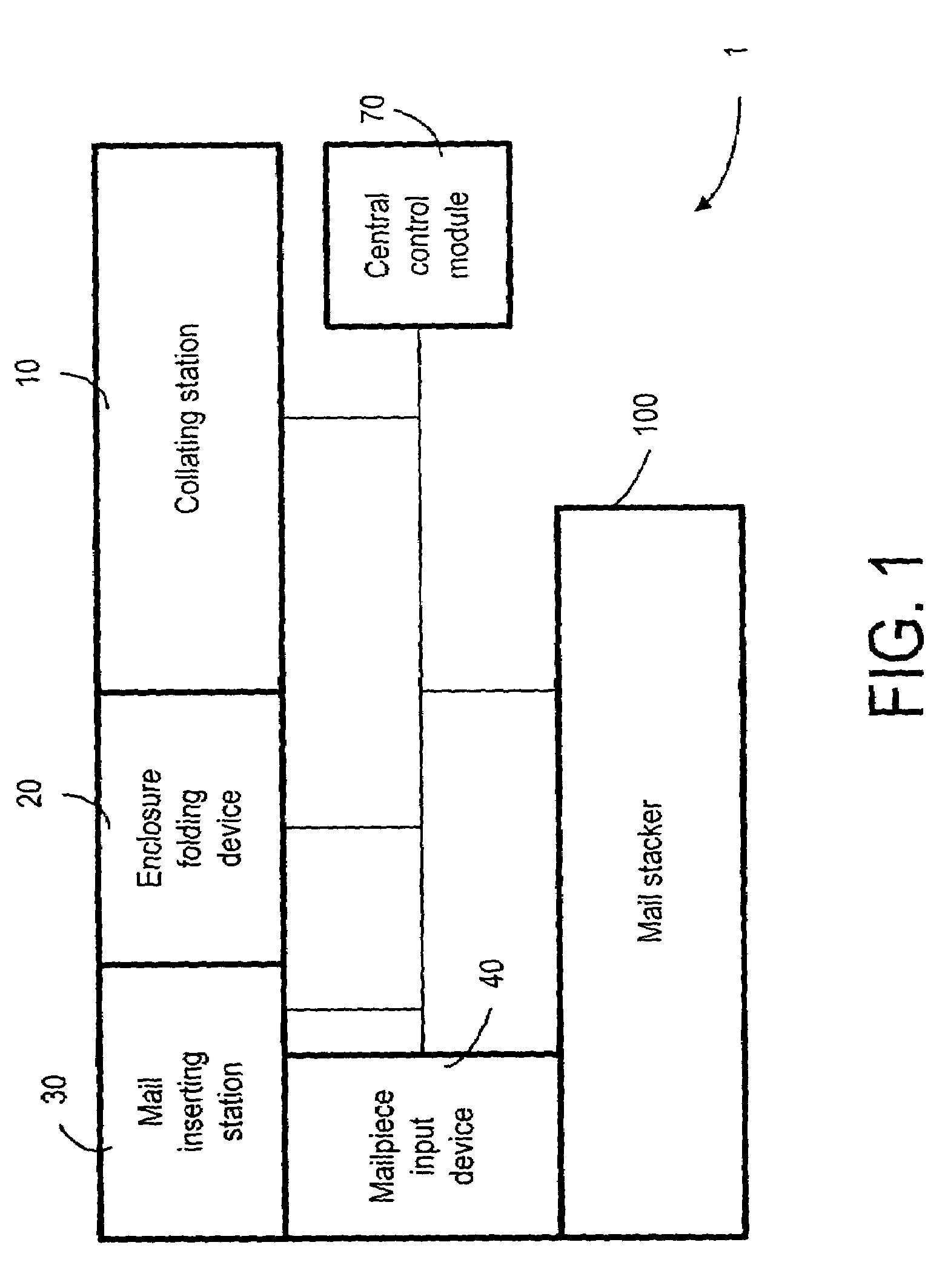
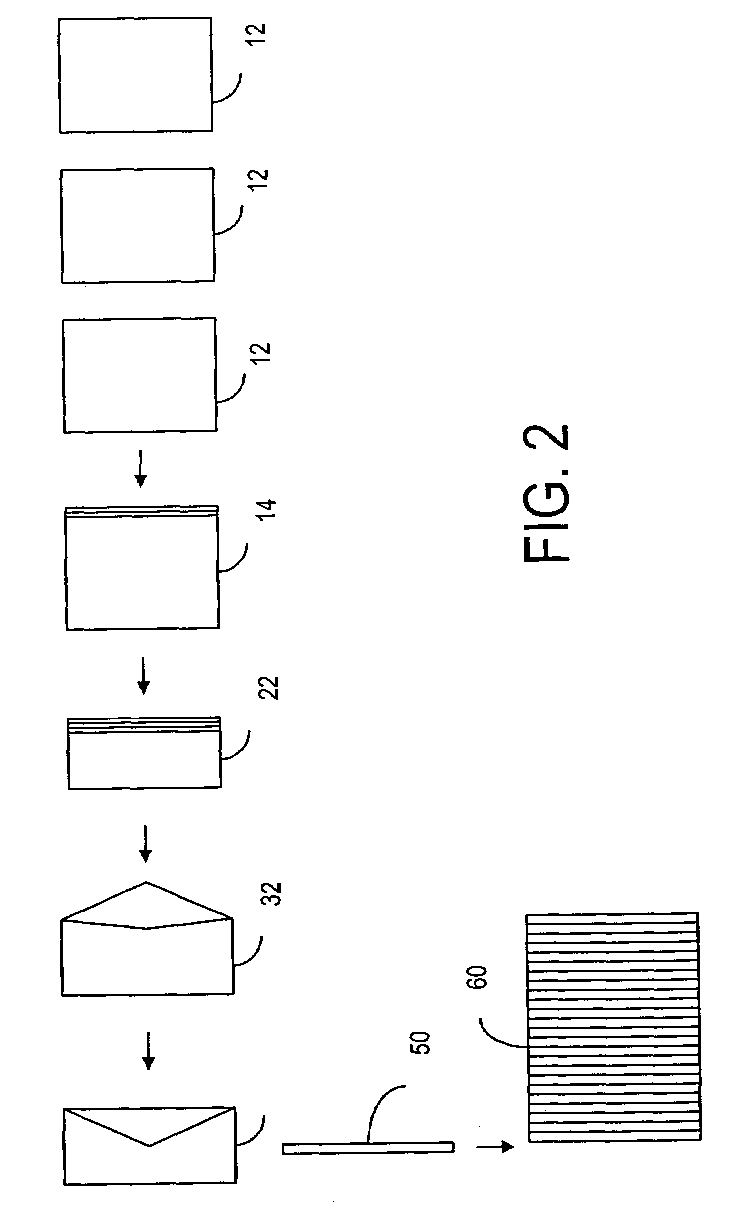
[0048]The method of adjusting the pack pressure in the mail stacker, according to present invention, is substantially based on the thickness of the incoming mailpieces 50 that are received into the stack 60. When the thickness is known, the displacement of the conveyor belt 130 along the moving direction 230 can be adjusted accordingly. It should be noted that the movement of the conveyor belts 130 along the moving direction 230 can be intermittent or continuous. Preferably, the movement is intermittent in that it is effected by a plurality of discrete steps, and each of the steps has a displacement distance. When the thickness is known, the displacement distance can be adjusted accordingly. Preferably, the information indicative of the thickness of the mailpiece 50 is obtained from the central control module 70, which monitors and controls the collation as it enters the chassis of the collation station 10 (FIG. 3). The collation is usually made up of a variable number of sheets of ...


PUM


Abstract

A method and device for stacking a plurality of vertically oriented mailpieces into a stack, wherein mailpieces are sequentially received into the back end of the stack. A paddle is used to support the front end of the stack in order to prevent the top mailpieces from falling forward. A conveyor belt is used to move the mailpieces in the stack and relieve the pack pressure so as to allow new mailpieces to join the stack. Information indicative of the mailpiece thickness is provided to a movement control module so that the conveyor belt is moved according to the thickness of the mailpieces received into the stack. As such, the pressure in the stack can be properly adjusted. The thickness information can be obtained from an upstream collator, for example.

Description

TECHNICAL FIELD[0001]The present invention relates generally to a mail stacking machine and, more particularly, to a vertical, or on-edge, stacker using a roller to move an input mailpiece into the back end of a mail stack.BACKGROUND OF THE INVENTION[0002]A mass mailing system generally comprises a mail inserting machine and a mail stacking machine. The mail inserting machine includes an envelope feeder and an enclosure document supply section. The envelope feeder is used to feed envelopes, one at a time, to an envelope insertion station. In the enclosure document supply section, a plurality of enclosure feeders is used to release enclosure documents to a chassis. The released documents are then gathered, collated and pushed by a plurality of pusher fingers to the envelope insertion station for insertion. Mail inserting machines are known in the art. For example, Roetter et al. (U.S. Pat. No. 4,169,341) discloses a mail inserting machine wherein documents are released onto a continu...

Claims


Application Information

Patent Timeline
Patent Type & Authority Patents(United States)
IPC IPC(8): B65H31/04B65H31/06
CPCB65H31/06B65H2511/13B65H2511/222B65H2701/1916B65H2220/01B65H2220/02
Inventor LEITZ, JERRYDEPOI, ARTHUR H.COMSTOCK, GARY
Owner DMT SOLUTIONS GLOBAL CORP
Learn More