Compressor

Active Publication Date: 2005-11-01
BITZER KUEHLMASCHINENBAU GMBH
View PDF10 Cites 205 Cited by
  • Summary
  • Abstract
  • Description
  • Claims
  • Application Information

AI Technical Summary

Benefits of technology

[0048]With respect to the fixing of the second bearing member in the inventive compressor, it has proven to be favorable when the second bearing member is connected to the first bearing member via the motor housing so that a precise alignment of the first bearing member and

Problems solved by technology

The problem with compressors of this type is that oil carried along by the refrigera

Method used


Image

  • Compressor
  • Compressor
  • Compressor

Examples


Embodiment Construction

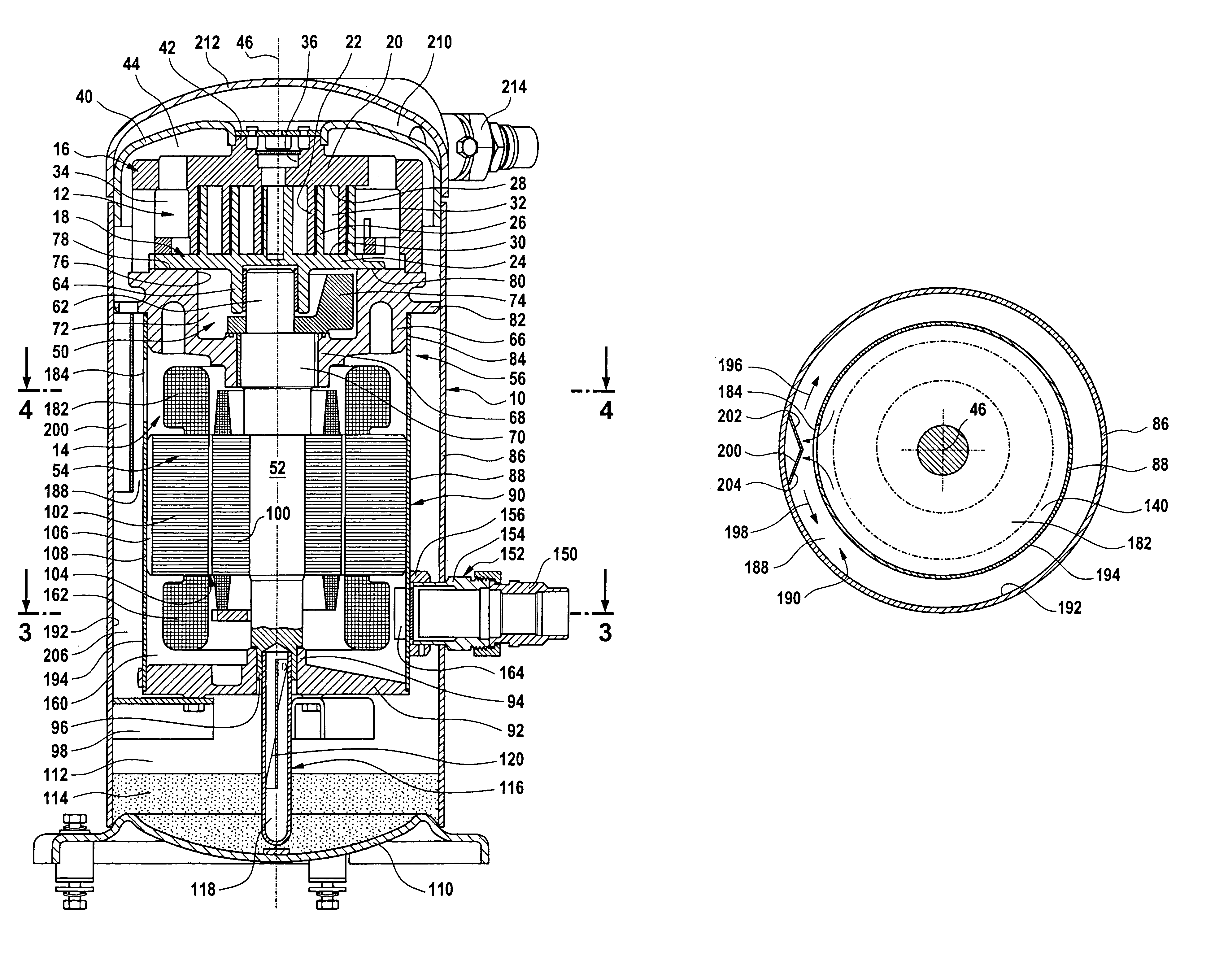
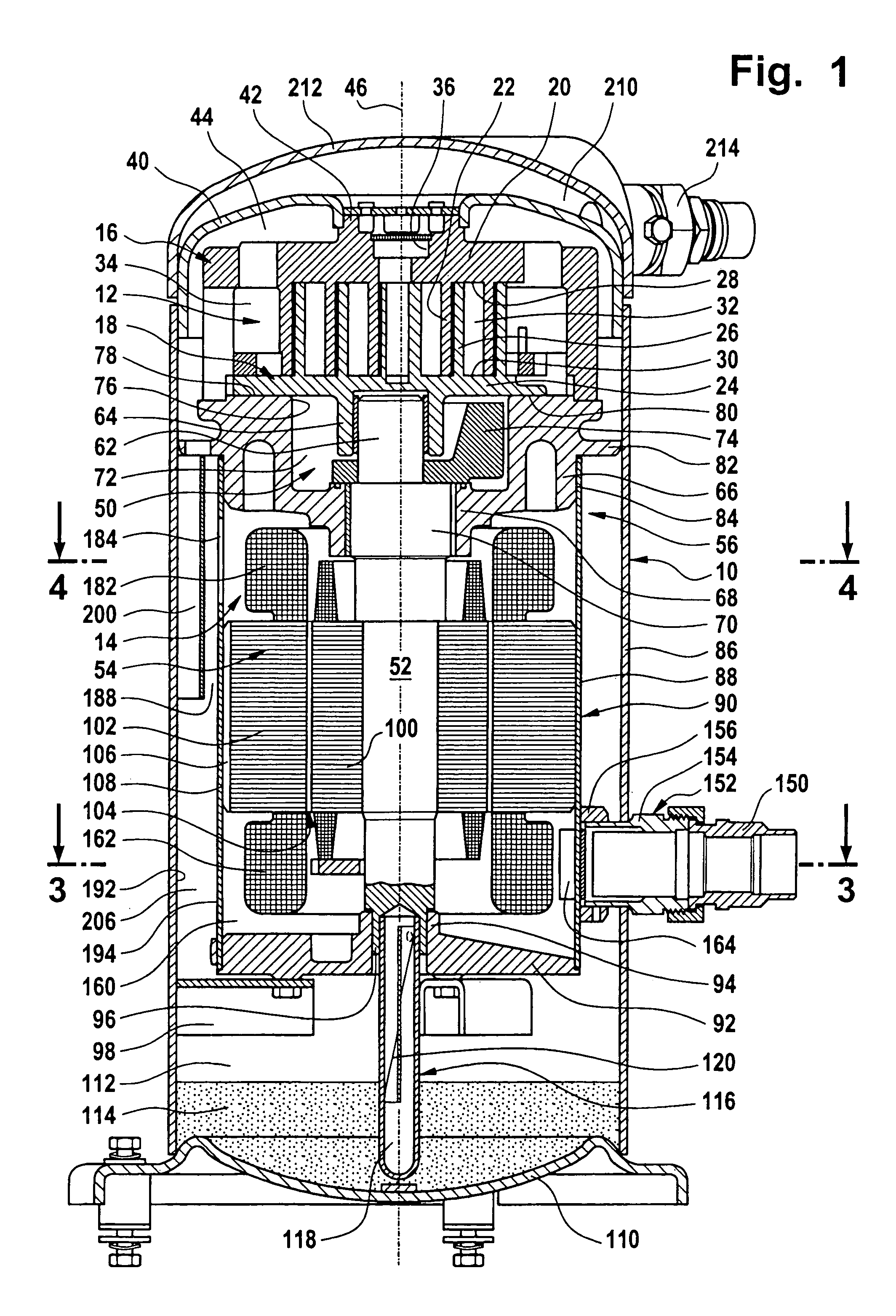
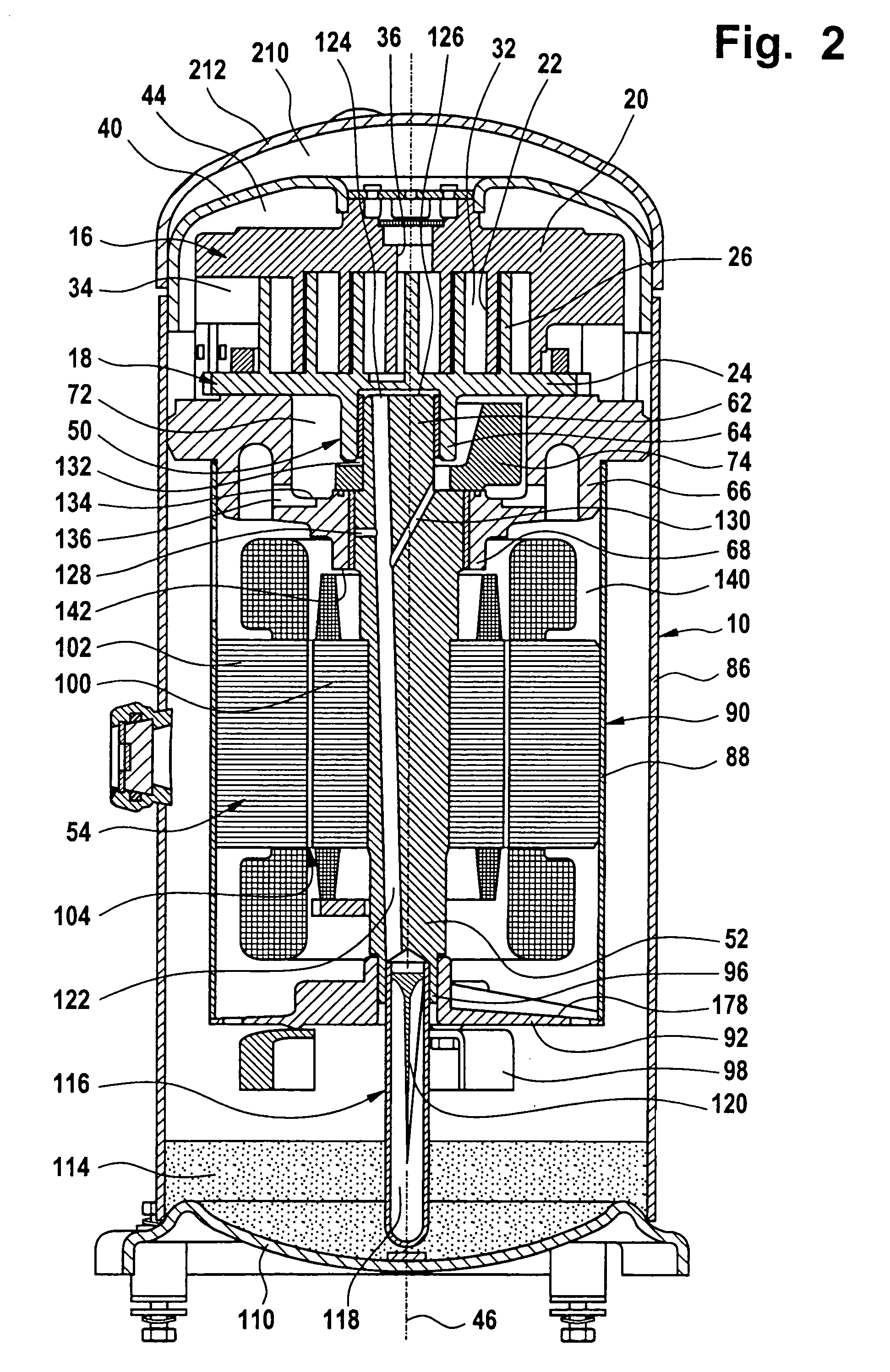
[0060]A first embodiment of an inventive compressor, illustrated in FIGS. 1 to 5, comprises an outer housing which is designated as a whole as 10 and in which a scroll compressor, which is designated as a whole as 12 and can be driven by a drive unit designated as a whole as 14, is arranged.

[0061]The scroll compressor 12 comprises a first compressor member 16 and a second compressor member 18, wherein the first compressor member 16 has a first scroll rib 22 which rises above a base 20 of the first compressor member and is designed in the form of a circular involute and the second compressor member 18 has a second scroll rib 26 which rises above a base 24 of the second compressor member and is designed in the form of a circular involute, wherein the scroll ribs 22, 26 engage in one another and abut sealingly on the base surface 28 and 30, respectively, of the respectively other compressor member 18, 16 so that chambers 32 are formed between the scroll ribs 22, 26 as well as the base ...


PUM


Abstract

In order to improve a compressor for refrigerant, comprising an outer housing, a scroll compressor arranged in the outer housing and having a first compressor member arranged stationarily in the outer housing and a second compressor member which is movable relative to the first compressor member, the compressor members each having a base and first and second scroll ribs, respectively, which rise above the respective base and engage in one another such that the second compressor member is movable relative to the first compressor member on an orbital path about a central axis for the purpose of compressing the refrigerant, a drive unit for the second compressor member having an eccentric drive, a drive shaft, a drive motor arranged in a motor housing and having drawn-in refrigerant flowing around it as well as a bearing unit for the drive shaft which comprises a first bearing member connected to the outer housing, in such a manner that the refrigerant drawn in by the scroll compressor is free from lubricating oil to as great an extent as possible it is suggested that the refrigerant flow through an oil separator, which is arranged in the outer housing between this and the drive unit, after flowing around the drive motor and prior to entering the scroll compressor.

Description

[0001]The present disclosure relates to the subject matter disclosed in German application No. 102 48 926.2 of Oct. 15, 2002, which is incorporated herein by reference in its entirety and for all purposes.BACKGROUND OF THE INVENTION[0002]The invention relates to a compressor for refrigerant, comprising an outer housing, a scroll compressor arranged in the outer housing and having a first compressor member arranged stationarily in the outer housing and a second compressor member movable relative to the first compressor member, these compressor members each having a base and first and second scroll ribs, respectively, which rise above the respective base and engage in one another such that the second compressor member is movable relative to the first compressor member on an orbital path about a central axis for the purpose of compressing the refrigerant, a drive unit for the second compressor member with an eccentric drive, a drive shaft, a drive motor arranged in a motor housing and ...

Claims


Application Information

Patent Timeline
IPC IPC(8): F04C29/02F04C18/02F04C23/00
CPCF04C29/126F04C18/0215F04C23/008F04C29/025Y10S418/01
Inventor KAMMHOFF, KARL-FRIEDRICHBALZ, GERNOTSCHARER, CHRISTIAN
Owner BITZER KUEHLMASCHINENBAU GMBH
Why Eureka
Try Eureka