
Multi-shot molded touch switch

a touch switch and multi-shot technology, applied in the direction of conductive pattern formation, emergency connection, pulse technique, etc., can solve the problems of non-activation of the switch, misalignment condition due to assembly errors or component stack-up tolerability,

Inactive Publication Date: 2005-11-01
LEAR CORP
View PDF8 Cites 51 Cited by
  • Summary
  • Abstract
  • Description
  • Claims
  • Application Information

AI Technical Summary

Benefits of technology

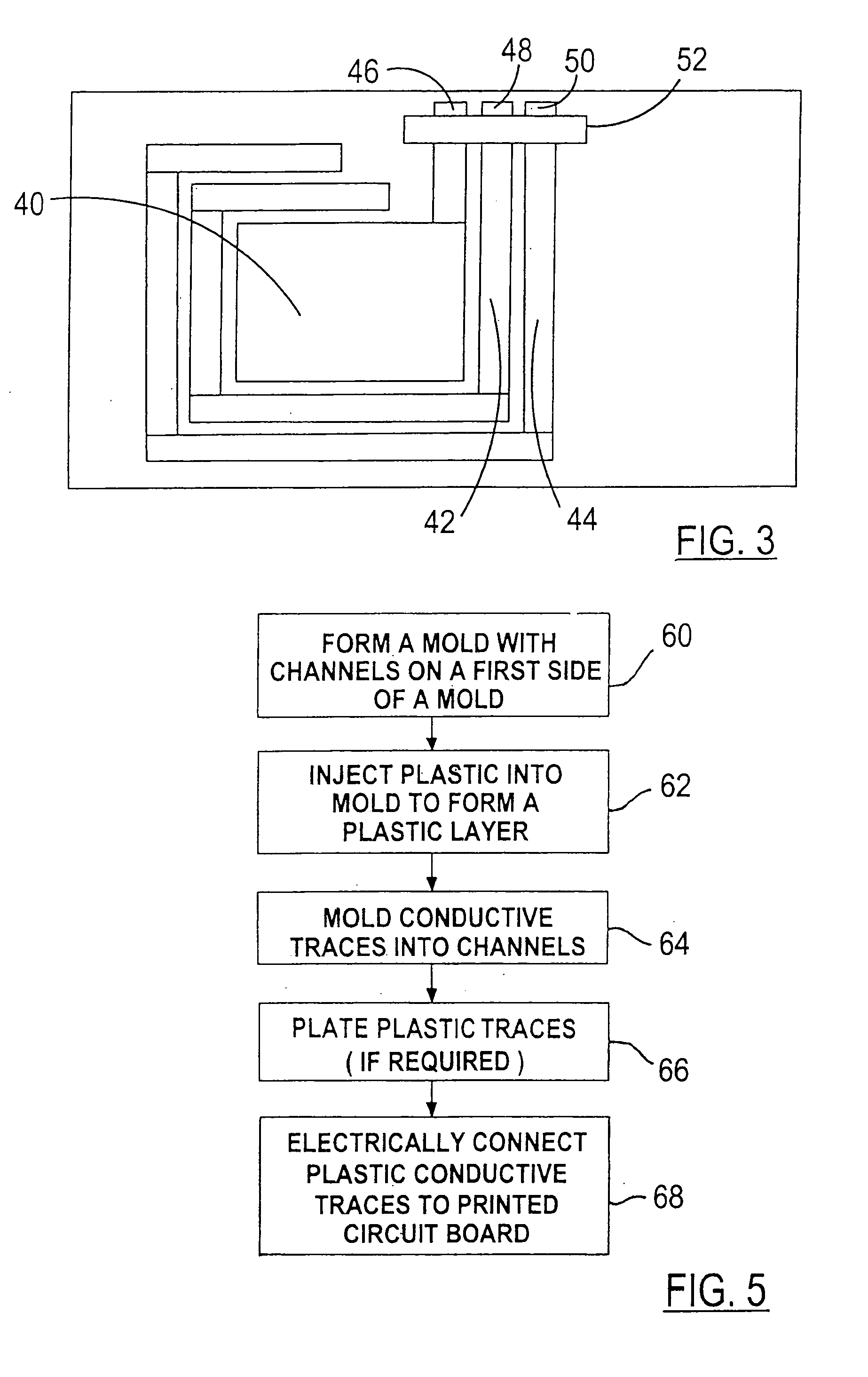
The present invention is about integrating a touch switch with a control panel using a multi-shot molding process. The touch switch is made by molding a plastic substrate in a first-shot mold with channels and then forming conductive plastic traces within those channels in a second-shot mold. The conductive plastic touch switch includes a plastic substrate with channels on its sides, conductive traces within the channels, and a printed circuit board attached to the conductive traces. The plastic substrate is made in the first mold and the conductive traces are in-molded in the second mold. This process allows for a more efficient and cost-effective way to make touch switches.

Problems solved by technology

Devices such as appliances have been known to use switches under the surface of a fascia of the appliance to create a sealed environment, however, these devices have been limited to a physical press and release operation.
As a result, a misalignment condition due to assembly errors or component stack-up tolerancing can occur between the capacitance sensor mounted below the surface fascia and the expected manual activation region identified by an exterior marking on the surface fascia.
This ultimately can lead to non-activation of the switch if the object is not properly placed within the generated electric field and dissatisfaction of an operator in attempting to actuate the switch.

Method used


Image

  • Multi-shot molded touch switch
  • Multi-shot molded touch switch
  • Multi-shot molded touch switch

Examples


Embodiment Construction

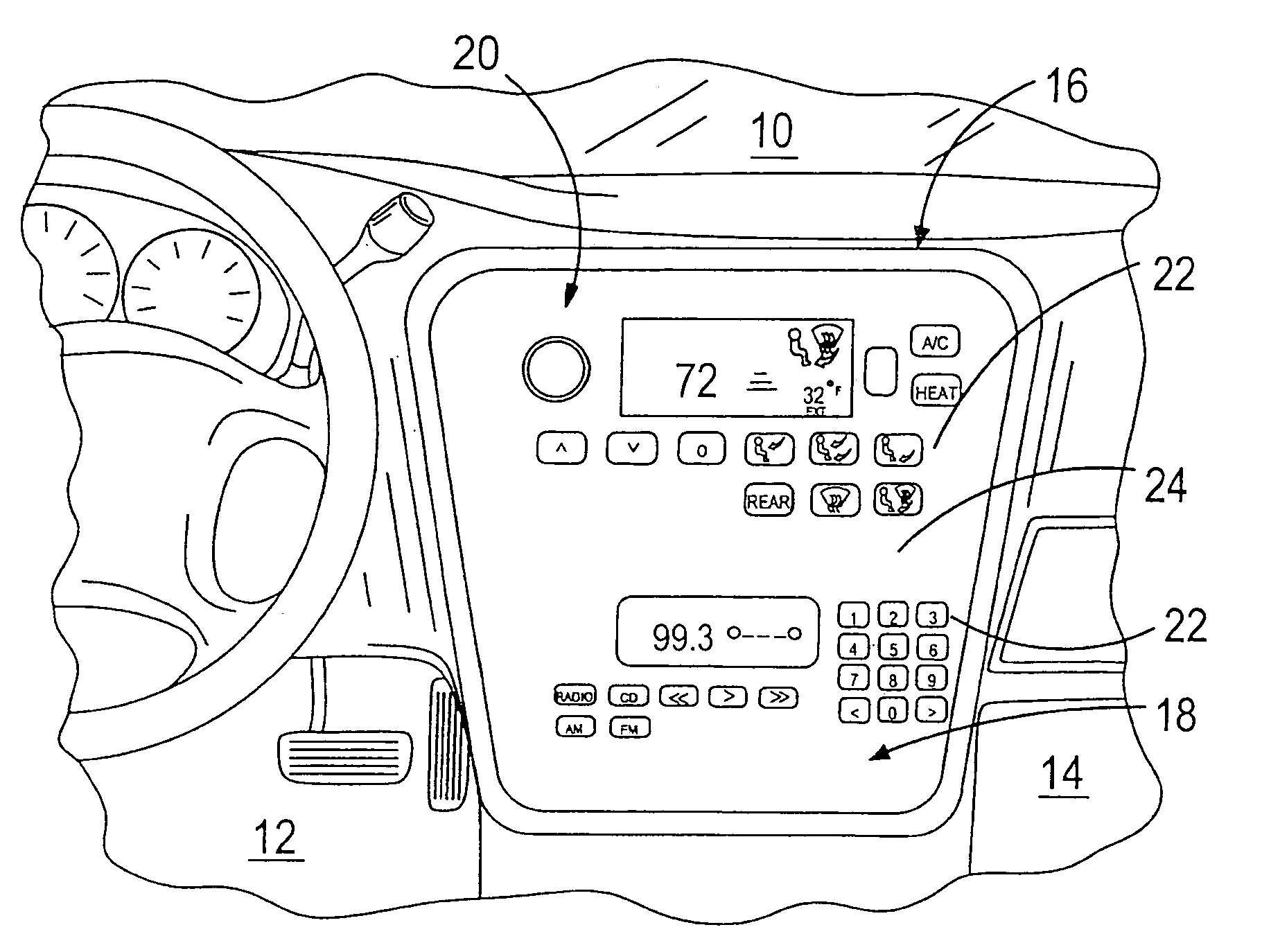
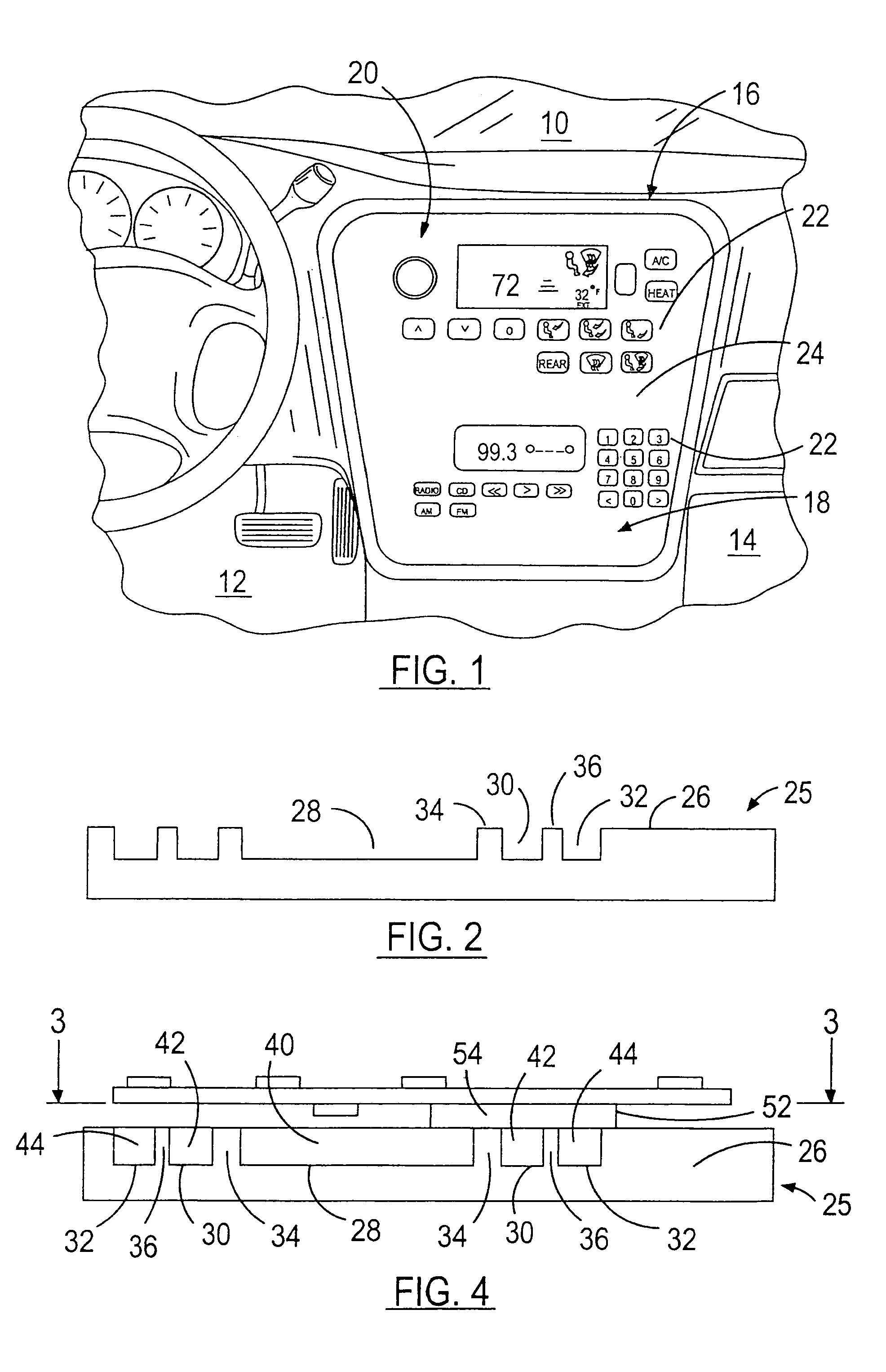
[0015]Referring now to the Drawings and particularly to FIG. 1, there is shown an interior passenger compartment 10 of a vehicle according to the present invention. The interior passenger compartment 10 comprises a front drivers seating area 12, a front passenger seating area 14, and a center accessory control unit 16. The center accessory control unit 16 includes a multimedia control unit 18 and a climate control unit 20. Both control units include a plurality of switches (e.g., buttons) 22 for controlling a specific feature of each respective accessory. For example, the multimedia control unit 18 typically includes switches for controlling multimedia selections such as CD, radio, AM / FM, fast forward, reverse, and preset memory. The climate control unit 20 typically includes switches for controlling temperature increase / decrease, defrost, A / C, blower motor, and blower motor output porting.

[0016]The plurality of switches 22 is disposed under a surface of a bezel 24 and is directed t...


PUM

PropertyMeasurementUnit
resistanceaaaaaaaaaa
conductiveaaaaaaaaaa
electric fieldaaaaaaaaaa

Abstract

A conductive plastic touch switch includes a plastic substrate having a first side surface including at least two channels formed within the first side surface and a second side surface including a manual activation region opposite of the at least two channels. At least two conductive traces are formed within the at least two channels, respectively. A printed circuit board is electrically attached to the at least two conductive traces. The plastic substrate is formed during a first mold process and said at least two conductive traces are in-molded during a second mold process.

Description

CROSS REFERENCE TO RELATED APPLICATIONS[0001]Not Applicable.STATEMENT REGARDING FEDERALLY SPONSORED RESEARCH[0002]Not Applicable.BACKGROUND OF THE INVENTION[0003]1. Field of the Invention[0004]The present invention relates in general to a touch sensitive switch, and more specifically, to a conductive plastic sensitive touch switch integrated with the surface of a control panel by a multi-shot mold process.[0005]2. Description of the Related Art[0006]Vehicle accessory input controls typically consist of devices which require rotating a control knob, depressing a control button, or sliding a mechanical or electro-mechanical control switch to operate or adjust a vehicle accessory device. An exterior casing or oversize buttons and knobs are typically used to dress up and conceal the gaps between the bezel and the movable components of the input control devices. Despite the addition of these facial coverings to make the appearance presentable and visually appealing, the plurality of inte...

Claims


Application Information

Patent Timeline
Patent Type & Authority Patents(United States)
IPC IPC(8): H01H19/00B29C45/16H01H13/88H05K1/09H05K3/10H05K3/12
CPCB29C45/16B29C45/1671B29C2045/169B29L2031/3443B29L2031/3493H01H13/88H01H2207/002H01H2229/046H01H2231/026H01H2239/006H05K1/095H05K3/107H05K3/1258
Inventor HEIN, DAVID A.CASS, MICHAEL W.DEPUE, TODD L.BANTER, CHARLES B.
Owner LEAR CORP
Learn More